(4) Install the radiator upper support crossmem-
ber. (Refer to 23 - BODY/EXTERIOR/GRILLE OPEN-
ING REINFORCEMENT - INSTALLATION)
(5) Install the upper radiator mounts to the cross-
member bolts, if removed. Tighten to 8 N·m (70 in.
lbs.).
(6) Install the radiator upper hose to the support
clip (2.4L engine).
RADIATOR FAN RELAY
DESCRIPTION
The radiator fan relay is a solid state type and is
located on the front bumper reinforcment (Fig. 22).
Refer to WIRING DIAGRAMS for a circuit sche-
matic.
OPERATION
The solid state radiator fan relay is controlled by
the Powertrain Control Module (PCM) by way of a
Pulse Width Modulated (PWM) signal. The relay con-
trol circuit supplies a 12 volt signal to the PCM. The
PCM then pulses the ground circuit to achieve fan on
time. The relay provides a voltage to the fan motors
which is proportional to the pulse width it receives
from the PCM. The duty cycle ranges from 30% for
low speed operation, then ramps-up to 100% for high
speed operation. This fan control system provides
infinitely variable fan speeds, allowing for improved
fan noise, A/C performance, better engine cooling,
and additional vehicle power.
To control operation of the relay, the PCM looks at
inputs from:
• Engine coolant temperature
• A/C pressure transducer
• Ambient temperature from the body controller
• Vehicle speed
• Transmission oil temperature
The PCM uses these inputs to determine when the
fan should operate and at what speed. For further
information on fan operation, (Refer to 7 - COOL-
ING/ENGINE/RADIATOR FAN - OPERATION).
REMOVAL
(1) Open hood.
(2) Disconnect and isolate the battery negative
cable.
(3) Remove the radiator crossmember to front fas-
cia closure panel.
(4) Disconnect the relay electrical connector (Fig.
22).
(5) Remove the rivet attaching the relay to the
front bumper beam (Fig. 22).
(6) Remove the relay.
INSTALLATION
CAUTION: The relay mounting location is designed
to dissipate heat. Ensure the relay is securely
attached to prevent relay “thermal” shutdown and
relay damage, resulting in possible engine over-
heating.
(1) Position relay and install a new rivet (Fig. 22).
(2) Connect electrical connector to relay.
(3) Install closure panel and attaching screws.
(4) Connect negative cable to battery.
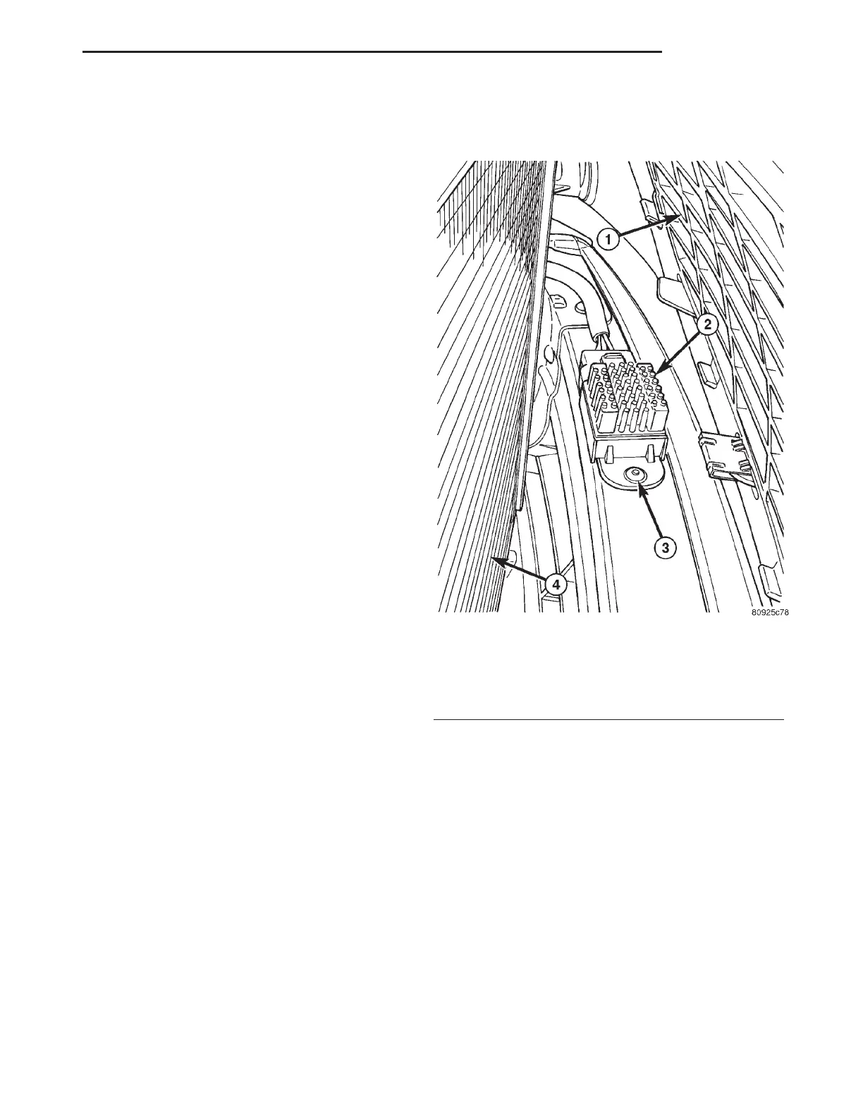
Fig. 22 Radiator Fan Relay
1 - FRONT FASCIA
2 - FAN RELAY
3 - RIVET
4 - A/C CONDENSER (FRONT SIDE)
RS ENGINE 7-31
RADIATOR FAN (Continued)