SPECIFICATIONS - HALF SHAFT - FRONT
TORQUE SPECIFICATIONS
DESCRIPTION N·m Ft. Lbs. In. Lbs.
Bolts, Caliper Adapter to Knuckle 169 125 -
Nut, Hub 244 180 -
Nuts, Front Wheel Lug 135 100 -
Nut, Tie Rod End to Knuckle 75 55 -
Nut, Strut Clevis to Knuckle 81 +90° 60 +90° -
CV BOOT - INNER
REMOVAL
(1) Remove the half shaft requiring boot replace-
ment from the vehicle. (Refer to 3 - DIFFERENTIAL
& DRIVELINE/HALF SHAFT - REMOVAL)
(2)
Remove large boot clamp which retains inner tri-
pod joint sealing boot to tripod joint housing and discard.
(3)
Remove small clamp which retains inner tripod
joint sealing boot to interconnecting shaft and discard.
(4) Remove the sealing boot from the tripod hous-
ing and slide it down the interconnecting shaft.
CAUTION: When removing the tripod joint housing
from the spider assembly, hold the bearings in
place on the spider trunions to prevent the bearings
from falling away.
(5) Slide the tripod joint housing off the spider
assembly and the interconnecting shaft (Fig. 12).
(6) Remove snap-ring which retains spider assem-
bly to interconnecting shaft (Fig. 13). Do not hit the
outer tripod bearings in an attempt to remove
spider assembly from interconnecting shaft.
(7) Remove the spider assembly from interconnect-
ing shaft. If spider assembly will not come off inter-
connecting shaft by hand, it can be removed by
tapping spider assembly with a brass drift (Fig. 14).
(8) Slide sealing boot off interconnecting shaft.
(9) Thoroughly clean and inspect spider assembly,
tripod joint housing, and interconnecting shaft for
any signs of excessive wear. If any parts show
signs of excessive wear, the half shaft assembly
will require replacement. Component parts of
these half shaft assemblies are not serviceable.
INSTALLATION
(1) Slide inner CV joint seal boot retaining clamp,
onto the interconnecting shaft. Then, slide the
replacement inner CV joint sealing boot onto the
interconnecting shaft. Inner CV joint seal boot
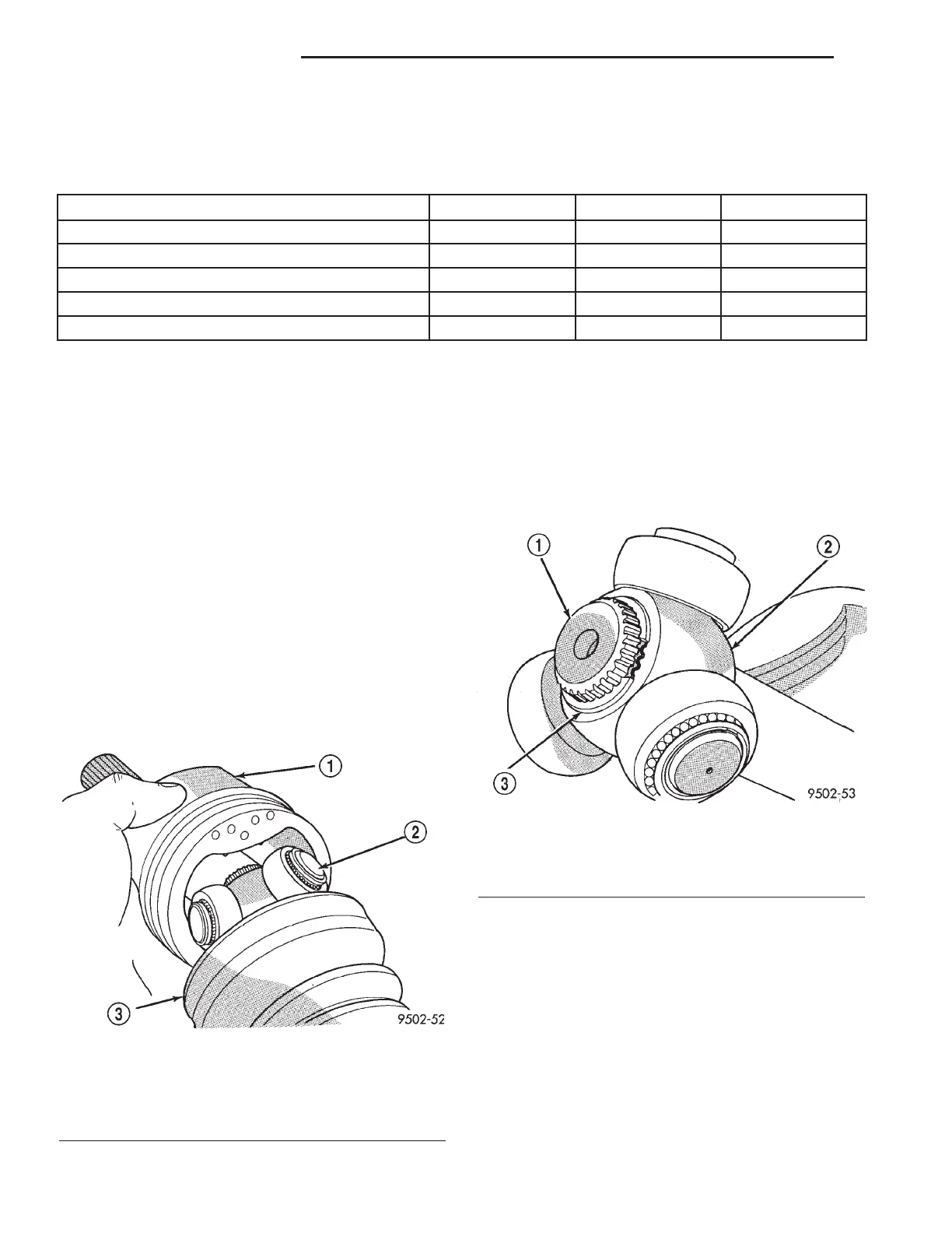
Fig. 12 Spider Assembly Removal from Tripod Joint
Housing
1 - TRIPOD JOINT HOUSING
2 - SPIDER ASSEMBLY
3 - SEALING BOOT
Fig. 13 Spider Assembly Retaining Snap-Ring
1 - INTERCONNECTING SHAFT
2 - SPIDER ASSEMBLY
3 - RETAINING SNAP-RING
3 - 6 HALF SHAFT - FRONT RS
HALF SHAFT - FRONT (Continued)