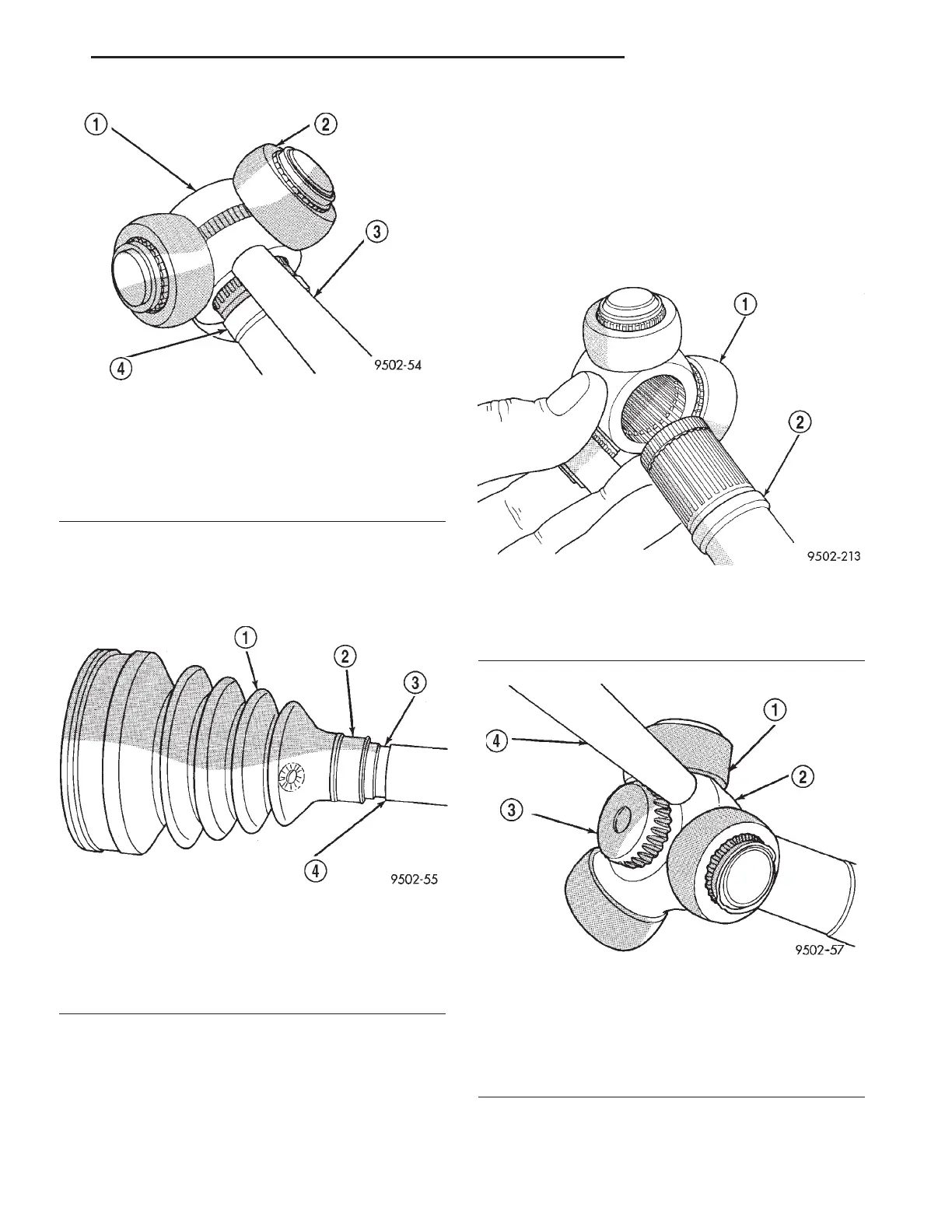
MUST be positioned on interconnecting shaft
so the raised bead on the inside of the small
diameter end of the seal boot is in mating
groove on interconnecting shaft (Fig. 15).
(2) Install spider assembly onto interconnecting
shaft (Fig. 16). Spider assembly must be installed on
interconnecting shaft far enough to fully install spi-
der retaining snap-ring. If the spider assembly will
not fully install on interconnecting shaft by hand, it
can be installed by tapping the spider body with a
brass drift (Fig. 17). Do not hit the outer tripod
bearings in an attempt to install spider assem-
bly on interconnecting shaft.
Fig. 14 Spider Assembly Removal from
Interconnecting Shaft
1 - SPIDER ASSEMBLY
2 - DO NOT HIT SPIDER ASSEMBLY BEARINGS WHEN
REMOVING SPIDER ASSEMBLY
3 - BRASS DRIFT
4 - INTERCONNECTING SHAFT
Fig. 15 Sealing Boot Installation on Interconnecting
Shaft
1 - SEALING BOOT
2 - RAISED BEAD IN THIS AREA OF SEALING BOOT
3 - GROOVE
4 - INTERCONNECTING SHAFT
Fig. 16 Spider Assembly Installation on
Interconnecting Shaft
1 - SPIDER ASSEMBLY
2 - INTERCONNECTING SHAFT
Fig. 17 Installing Spider Assembly on
Interconnecting Shaft
1 - DO NOT HIT BEARINGS WHEN INSTALLING THE SPIDER
ASSEMBLY
2 - SPIDER ASSEMBLY
3 - INTERCONNECTING SHAFT
4 - BRASS DRIFT
RS HALF SHAFT - FRONT 3-7
CV BOOT - INNER (Continued)
 Loading...


