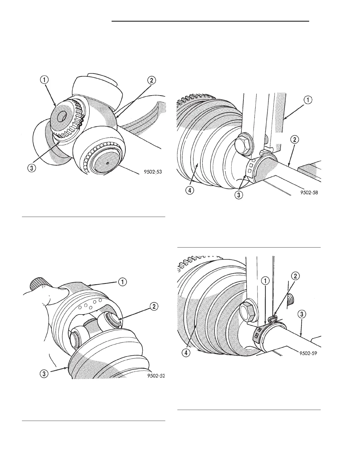
(3) Install the spider assembly to interconnecting
shaft retaining snap-ring into groove on end of inter-
connecting shaft (Fig. 18). Be sure the snap-ring is
fully seated into groove on interconnecting shaft.
(4) Distribute 1/2 the amount of grease provided in
the seal boot service package (DO NOT USE ANY
OTHER TYPE OF GREASE) into tripod housing. Put
the remaining amount into the sealing boot.
(5) Align tripod housing with spider assembly and
then slide tripod housing over spider assembly and
interconnecting shaft (Fig. 19).
(6) Install inner CV joint seal boot to interconnect-
ing shaft clamp evenly on sealing boot.
(7) Place crimping tool C-4975-A over bridge of
clamp (Fig. 20).
(8) Tighten nut on crimping tool C-4975-A until
jaws on tool are closed completely together, face to
face (Fig. 21).
Fig. 18 Spider Assembly Retaining Snap-Ring
Installed
1 - INTERCONNECTING SHAFT
2 - SPIDER ASSEMBLY
3 - RETAINING SNAP-RING
Fig. 19 Installing Tripod Housing on Spider
Assembly
1 - TRIPOD JOINT HOUSING
2 - SPIDER ASSEMBLY
3 - SEALING BOOT
Fig. 20 Crimping Tool Installed on Sealing Boot
Clamp - Typical
1 - SPECIAL TOOL C-4975-A
2 - INTERCONNECTING SHAFT
3 - CLAMP
4 - SEALING BOOT
Fig. 21 Sealing Boot Retaining Clamp Installed -
Typical
1 - CLAMP
2 - JAWS OF SPECIAL TOOL C-4975-A MUST BE CLOSED
COMPLETELY TOGETHER HERE
3 - INTERCONNECTING SHAFT
4 - SEALING BOOT
3 - 8 HALF SHAFT - FRONT RS
CV BOOT - INNER (Continued)
 Loading...


