3.2.- INSTALLATION
The device will be installed on a panel (92
+0.8
x 92
+0.8
mm panel drill hole, in compliance with DIN
43700). All connections are located inside the electric panel.
Terminals, opening covers or removing elements can expose parts that are haz-
ardous to the touch while the device is powered. Do not use the device until it is
fully installed.
The device must be connected to a power circuit that is protected with gl (IEC 269) or M type
fuses with a rating of 0.5 to 2 A. It must be tted with a circuit breaker or equivalent device, in
order to be able to disconnect the device from the power supply network.
The power and voltage measuring circuit must be connected with cables that have a minimum
cross-section of 1mm
2
.
The secondary line of the current transformer will have a minimum cross-section of 2.5 mm
2
.
The temperature rating of insulation of wires connected to the device will be at minimum 62ºC.
3.3.- CVM-C10-FLEX: ROGOWSKI SENSORS
The CVM-C10-FLEX model measures currents using exible sensors, based on the Rogowski
coil principle.
The exibility of the sensor allows it to measure an alternating current irrespective of the posi-
tion of the conductor.
The unit has 2 measurement scales with automatic changes,
Table 2:Rogowski sensors for current measurements.
Type Code Scale Accuracy
(1)
Full scale Length Diameter
FLEX-MAG70 M818110041500
0 ... 500 A~ ± 1% of the range
1000 A / 100 mV~ 2 m 70 mm
500 ... 1000 A ~ ± 1% of the range
FLEX-MAG120 M818120041500
0 ... 500 A ~ ± 1% of the range
1000 A / 100 mV~ 2 m 120 mm
500 ... 1000 A ~ ± 1% of the range
(1)
The measurement accuracy is for the sensor in its optimal position, with no external electric or magnetic
elds and within the working temperature range.
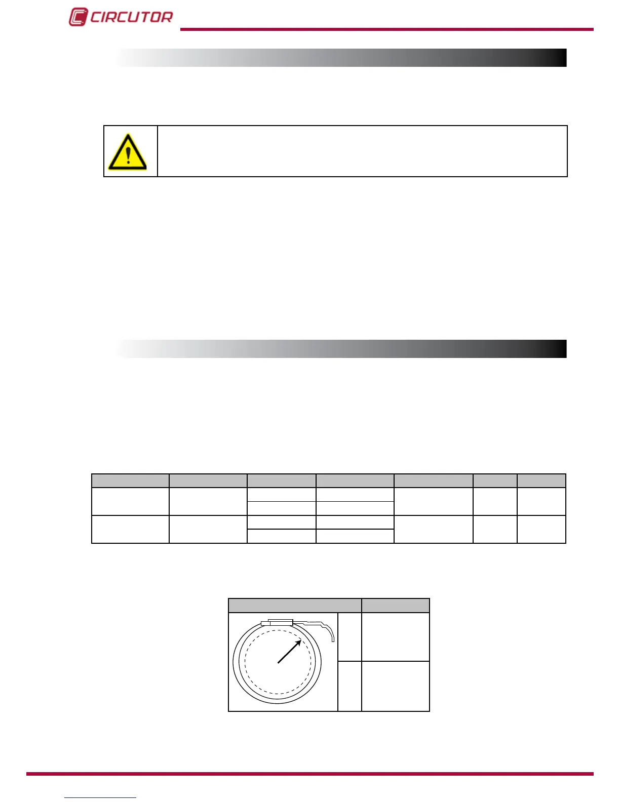
Table 3:Position error.
Position Error
A
B
A ± 1%
B A ± 3%
10