• Voltage harmonics L1- L2 - L3
• Current harmonics L1- L2 -L3
4.7.- INPUTS
The CVM-C10 has two digital inputs (terminals 12 and 13 on
Figure 1, Figure 2 and Figure 3)
that can be programmed to operate as a logic or tariff selection input.
If congured as a logic input, the device displays the status of that input.
See
“4.9.27. Operating mode of digital input 1” and “4.9.28. Operating mode of digital input 2”
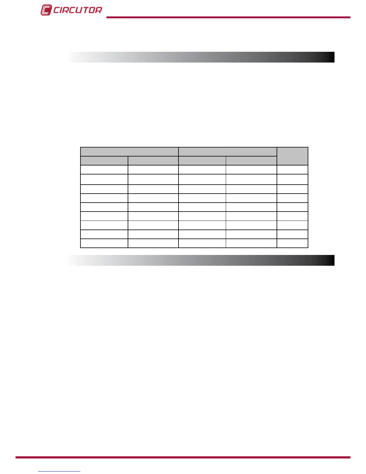
The selected tariff can be determined in accordance with the status of the inputs, as shown in
Table 15.
Table 15: Selecting the tariff in accordance with the input status.
IN1, Input 1 IN2, Input 2
Tariff
Logic input Tariff selection Logic input Tariff selection
x x T1
x 0 T1
x 1 T3
0 x T1
1 x T2
0 0 T1
0 1 T3
1 0 T2
1 1 T1
4.8.- OUTPUTS
The device features:
Two alarm relays (terminals 3, 4 and 5, as shown in
Figure 1, Figure 2 and Figure 3),
fully programmable, see
“4.9.23. Programming alarm 1 (Relay 1)” and “4.9.24. Program-
ming alarm 2 (Relay 2)”
Two digital outputs, optoisolated NPN transistors (terminals 6, 7 and 8 on Figure 1
and Figure 3
), fully programmable, see “4.9.25. Programming alarm 3 (Digital output T1)”
and “4.9.26. Programming alarm 4 (Digital output T2)”.
Note: The digital outputs are not available on models CVM-C10-ITF-IN and CVM-C10-FLEX
44