3.4.- UNIT TERMINALS
3.4.1.- LIST OF TERMINALS, CVM-C10-ITF, CVM-C10-MC AND CVM-C10-mV MODELS
Table 5:List of terminals of the CVM-C10-ITF, CVM-C10-MC and CVM-C10-mV.
Device terminals
1 : A1 Auxiliary power supply. 13: I2, digital input 2 / tariff selection
2: A2 Auxiliary power supply. 14: V
L1,
Voltage input L1
3: Rc, Common relay output 15: V
L2,
Voltage input L2
4: R2, Relay output 2
16: V
L3
,Voltage input L3
5: R1, Relay output 1
17: N, Neutral
6: CT, Common digital output.
18: S1
,
Current input L1
7: T2, Digital output 2
19: S2, Current input L1
8: T1, Digital output 1
20: S1, Current input L2
9: A(+), RS485
21: S2, Current input L2
10: B(-), RS485
22: S1, Current input L3
11: GND, for RS485 and digital inputs
23: S
2
, Current input L3
12: I1, digital input 1 / tariff selection
1
2
3 4 5 6 7
8
9
10 11 12
13
14 15 16 17
18 19 20 21 22 23
POWER SUPPLY
INPUTS
A(+) B(-)
GND
RS485
S1 S2
S1 S2
S1 S2
L1
P1 P2
L2
L3
300V
~
Ph-NPh-Ph
520V
~
NV
L3L2
V
L1
V
P1 P2
P1 P2
I1 I2
OUTPUTS
Rc R2 R1 Tc T2 T1
S0-
S0+ S0+
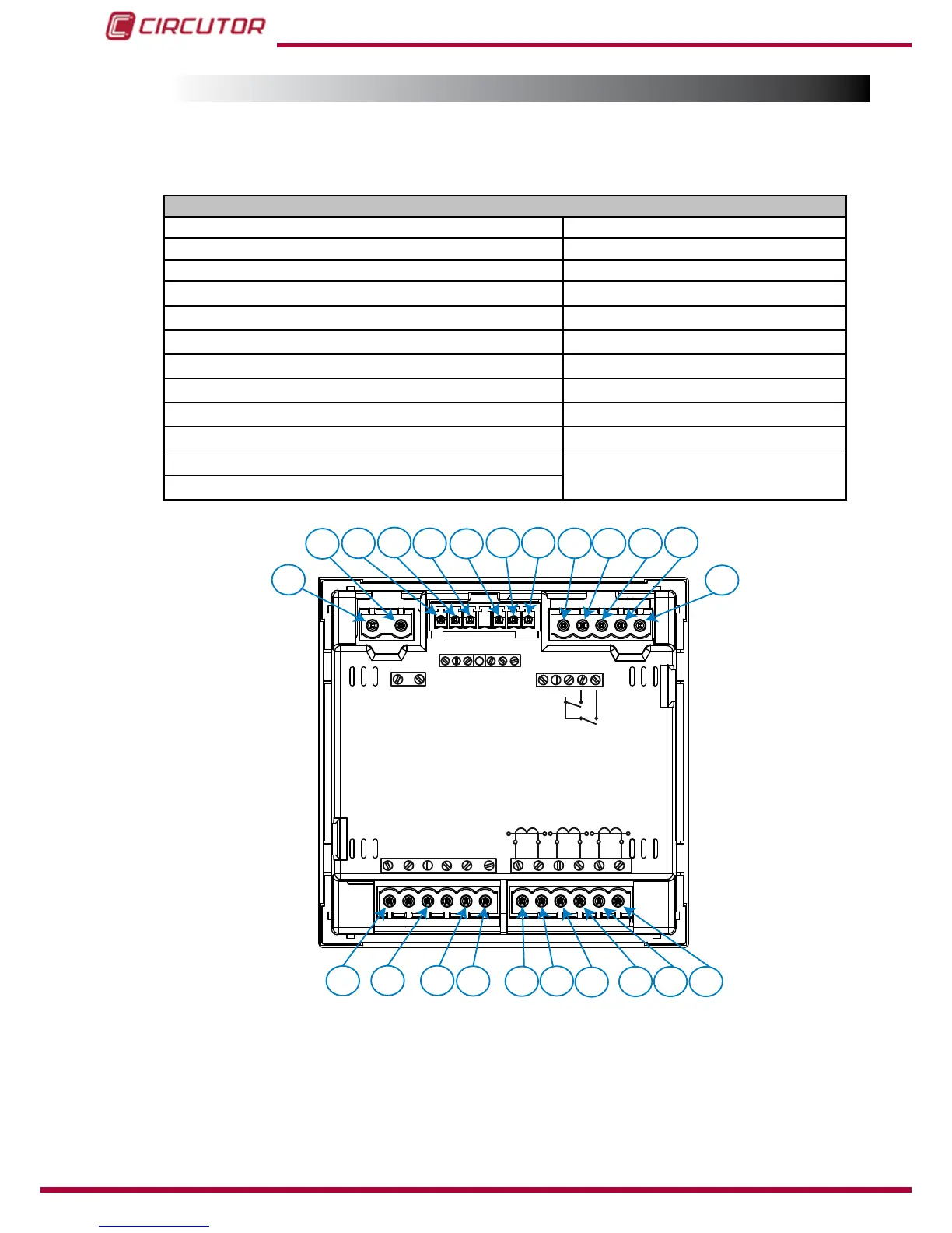
Figure 1:Terminals of the CVM-C10-ITF, CVM-C10-MC and CVM-C10-mV.
12