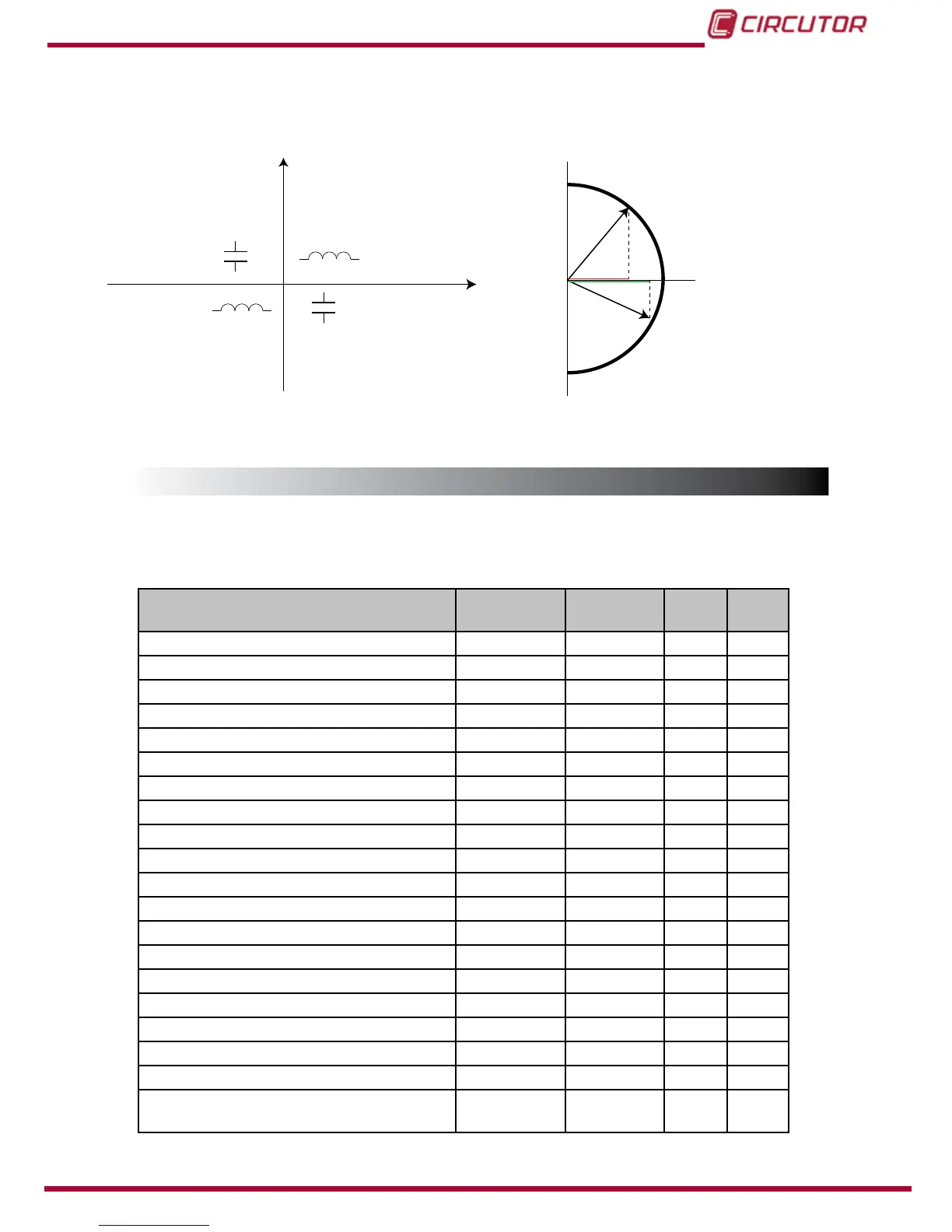
IEEE measurement convention
Q
P
Q1Q2
Q3
Q4
P < 0 Q > 0 PF > 0
Capacitive
Capacitive
Inductive
Inductive
P < 0 Q < 0 PF < 0 P > 0 Q < 0 PF > 0
P > 0 Q > 0 PF < 0
Operation in the 4 quadrants (Q1, Q2, Q3, Q4)
0 -
0 +
cos φ < 0
cos φ > 0
Q1
Q4
- 1
+ 1
cos φ values in the receiver operating mode (Q1,Q4)
Figure 21:Convenio de medida IEEE.
4.1.- MEASURING PARAMETERS
The device displays the electrical parameters shown in
Table 8.
Table 8: Measuring parameters of the CVM-C10.
Parameter Units
Phases
L1-L2-L3
Total
III
N
Phase-neutral voltage Vph-N
Phase-phase voltage Vph-ph
Current A
Frequency Hz
Active power M/kW
Apparent power M/kVA
Total Reactive Power M/kvar
Total Reactive Power - Consumption M/kvar
Total Reactive Power - Generation M/kvar
Total Inductive Reactive Power M/kvarL
Inductive Reactive Power - Consumption M/kvarL
Inductive Reactive Power - Generation M/kvarL
Total Capacitive Reactive Power M/kvarC
Capacitive Reactive Power - Consumption M/kvarC
Capacitive Reactive Power - Generation M/kvarC
Power factor PF
Cos φ φ
THD % Voltage % THD V
THD % Current % THD A
Harmonic Breakdown - Voltage
(up to the 31st order harmonic)
harm V
31