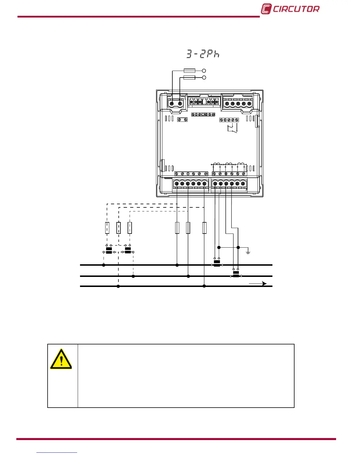
3.5.9.- MEASURING TWO-PHASE NETWORKS WITH A 3-WIRE CONNECTION,
CVM-C10-ITF, CVM-C10-MC AND CVM-C10-mV MODELS.
Measurement system:
Power
Supply
V
L1 VL2 N
L1
L2
N
POWER SUPPLY
INPUTS
A(+) B(-)
GND
RS485
S1 S2
S1 S2
S1 S2
L1
P1 P2
L2
L3
300V
~
Ph-NPh-Ph
520V
~
NV
L3L2
V
L1
V
P1 P2
P1 P2
I1 I2
OUTPUTS
Rc R2 R1 Tc T2 T1
S0-
S0+ S0+
VL1 N
V
L2
a
b
A
B
a b
A B
S1 S2
P1
P2
S1 S2
P1
P2
LOAD
Figure 12: Measuring Two-Phase Networks with a 3-wire connection, CVM-C10-ITF, CVM-C10-MC and CVM-C10-mV
models.
CVM-C10-ITF model:
The transformer secondary value must be 5A or 1A
CVM-C10-MC model:
The MC transformer secondary value is set to 0.250 A (xed value)
CVM-C10-mV model:
The transformer secondary value must be 0.333 V
23