4.3.2. ANALOGUE BAR
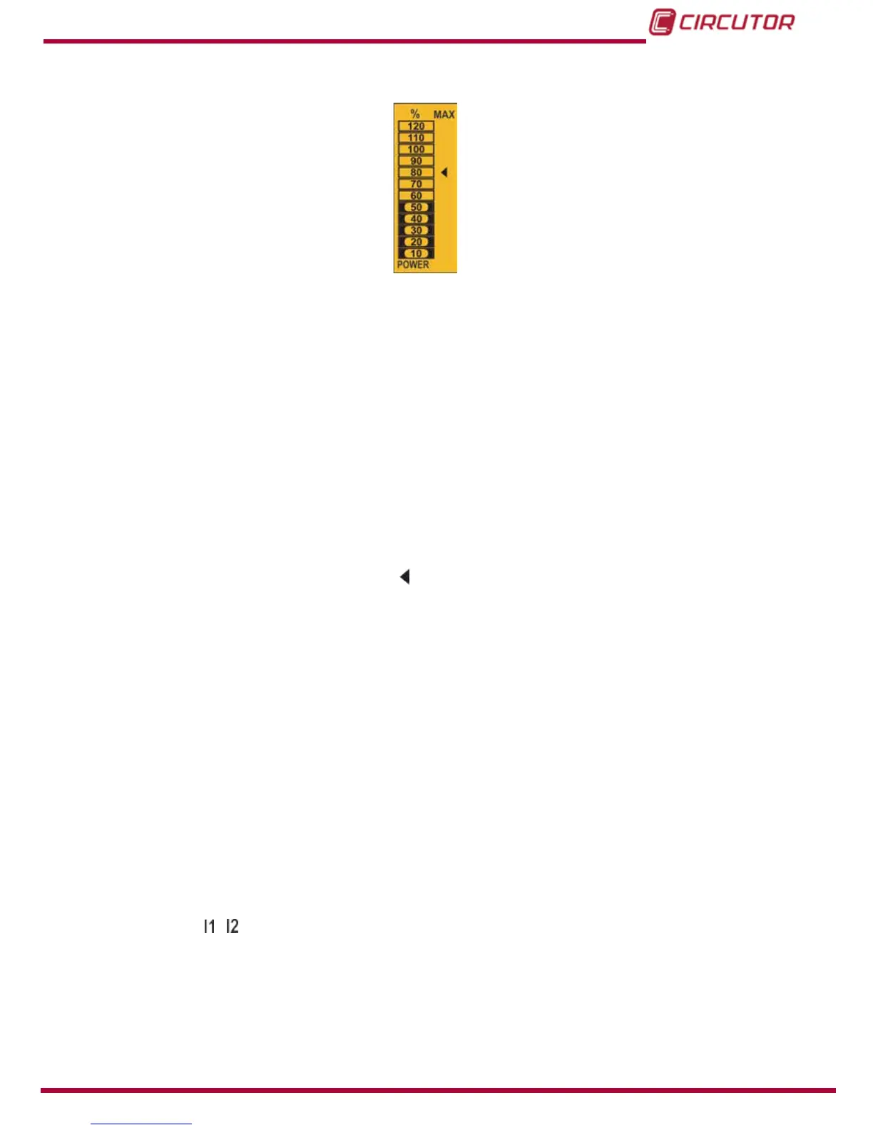
Figure 24: Analogue Bar
The analogue bar displays two parameters:
Current power of the installation in %
This parameter is displayed in 12 divisions, each one represents 10%, into which the
analogue bar is divided.
The device calculates the current power of the installation using the formula:
P = V*I*cos(φ)
Where the voltage and the cos(φ) are the installation’s current values.
The current is referenced in its full scale. (100% is the full scale of the device and a value
above 100% indicates that it is out of range).
The maximum system demand reached, i.e., the maximum power value
reached since the device was started, expressed as a percentage.
This value is displayed with the icon .
The value and the maximum and minimum values are reset. (“4.9.15. Deleting maximum
and minimum values”
)
Example: Figure 24 shows that the installation performance is 50% and that the maximum de-
mand of the system is 80%.
4.3.3. OTHER SYMBOLS ON THE DISPLAY
The following are also shown on the display:
Type of installation
The type of installation to which the device is connected can be selected on the program-
ming menu, (“4.9.9. Type of installation”). The selected type is shown on the top left of
the display.
State of digital inputs
If the digital inputs have been activated, the top left of the display will show
the icons that indicate that the digital input is active.
35