Digital I/O
27
12.2 Outputs
The tester’s outputs are “sinking” (open collector) outputs. When activat-
ed they will connect (or sink) to ground, in eect turning ON the output
circuit. The outputs can sink up to a nominal 24 volts at 500 milliamps.
To limit the output current, always ensure adequate resistance between
power supply and the output.
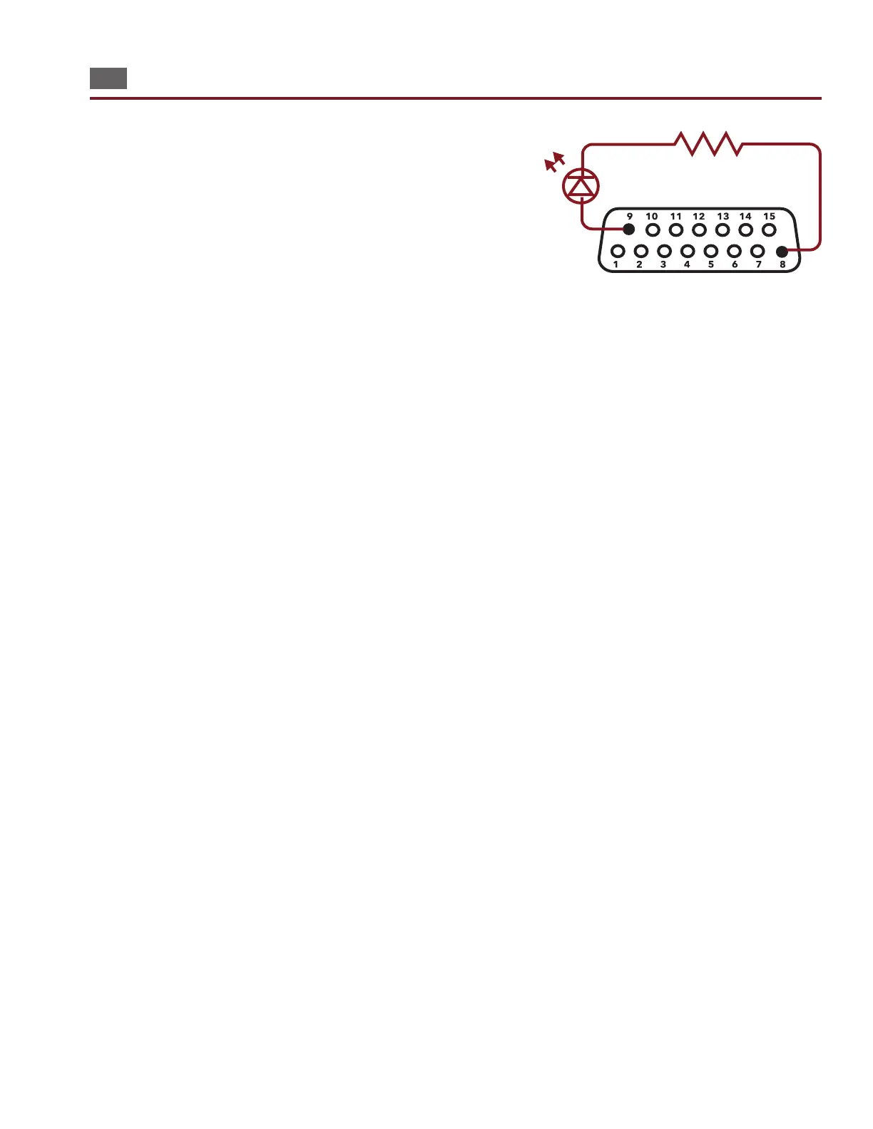
As an example, let’s say you want to light an LED to indicate a bad test.
You will want to connect the LEDs to pins 8 (output for bad test) and 9
(+5V). The LED requires only 20 mA, so we can use the +5 DC volt supply
on the digital I/O port to power the circuit. Use a resistor in series with the
LED to limit the current going through it. How do you choose the resistor?
The LED in this instance has a forward bias voltage drop of two volts; there-
fore, three volts must drop across the current limiting resistor. Knowing the
voltage drop is three volts across the resistor and the desired current is 20
mA, Ohms Law can be used to determine the resistor value.
V/I = R
3V/20mA = 150 Ohms
In this example, you would use a 150 Ohms resistor to limit the current through the LED.
When a test completes, the tester will pull the output to ground allowing current to ow in the circuit, and the LED will
turn on. If the test fails, pin 8 will be pulled low. Pin 7 will be pulled low when a test passes. These results will only activate
when all tests nish (including after the intermittents test is complete).
Example of Digital I/O outout wired with LED.