26
Cirris 4200 Series User Manual
12. Digital I/O
With digital I/O, the tester can start a test based on input from an external switch, such as a foot pedal. Through its outputs,
the tester can also activate devices such as LEDs.
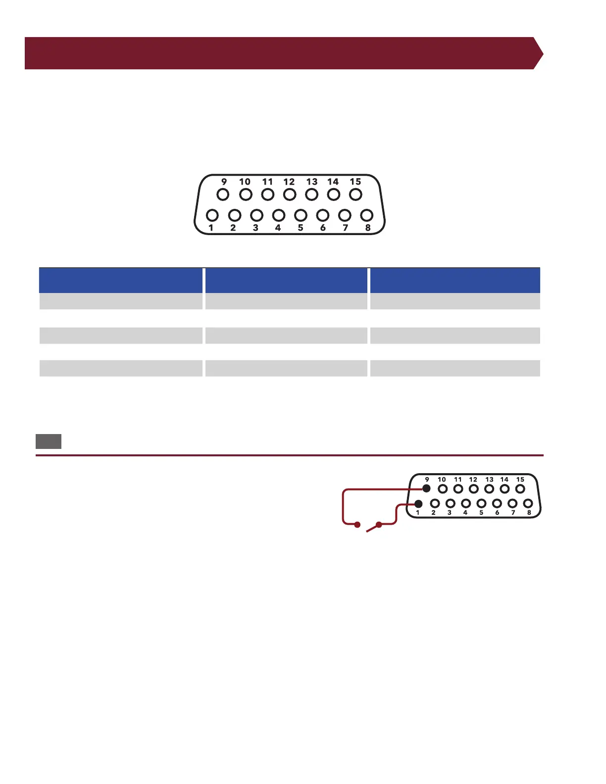
The digital I/O port is located on the back of the tester. The pinout is as follows:
Pin Function Pin Function Pin Function
1 Input Switch LV Start 6 Output 11 Output
2 Input Switch HV Start 7 Output for good test 12 Power + 10 VDC, 100 mA max.
3 Input 8 Output for bad test 13 N/A
4 Input 9 Power + 5 VDC, 100 mA max 14 Ground
5 Output 10 Output 15 Ground
To use the External Switch input, you must set the test program’s Start Condition to Press Button.
12.1 Inputs
The 4250 tester has two inputs, pins 1 and 2. The low voltage input is
on pin 1 of the digital I/O connector. If a DC +5 volt (logic high) is ap-
plied to pin 1, the tester behaves as if START TEST were pressed. You can
use the DC +5 volt power source on the digital I/O connector to supply
the DC +5 voltages through the switch circuit. Make sure you wire your
external switch so it is normally open. Do not apply an AC voltage to
the input.
Example of Digital I/O input wired with start switch.