SpecificationItem
ROHS 6/6Environmental
Front and Rear Panel Components
This article describes the components on the front and rear panels of the vEdge 100b router.
Front Panel
The front panel of the vEdge 100b router has the DC power socket, chassis status LEDs, and reset button. See
Chassis Views for the location of these components.
DC Power Socket
The front panel of the vEdge 100b router has a DC power input socket for plugging in the external 12-Volt
AC-DC power adapter that is shipped with the router.
Chassis Status LEDs
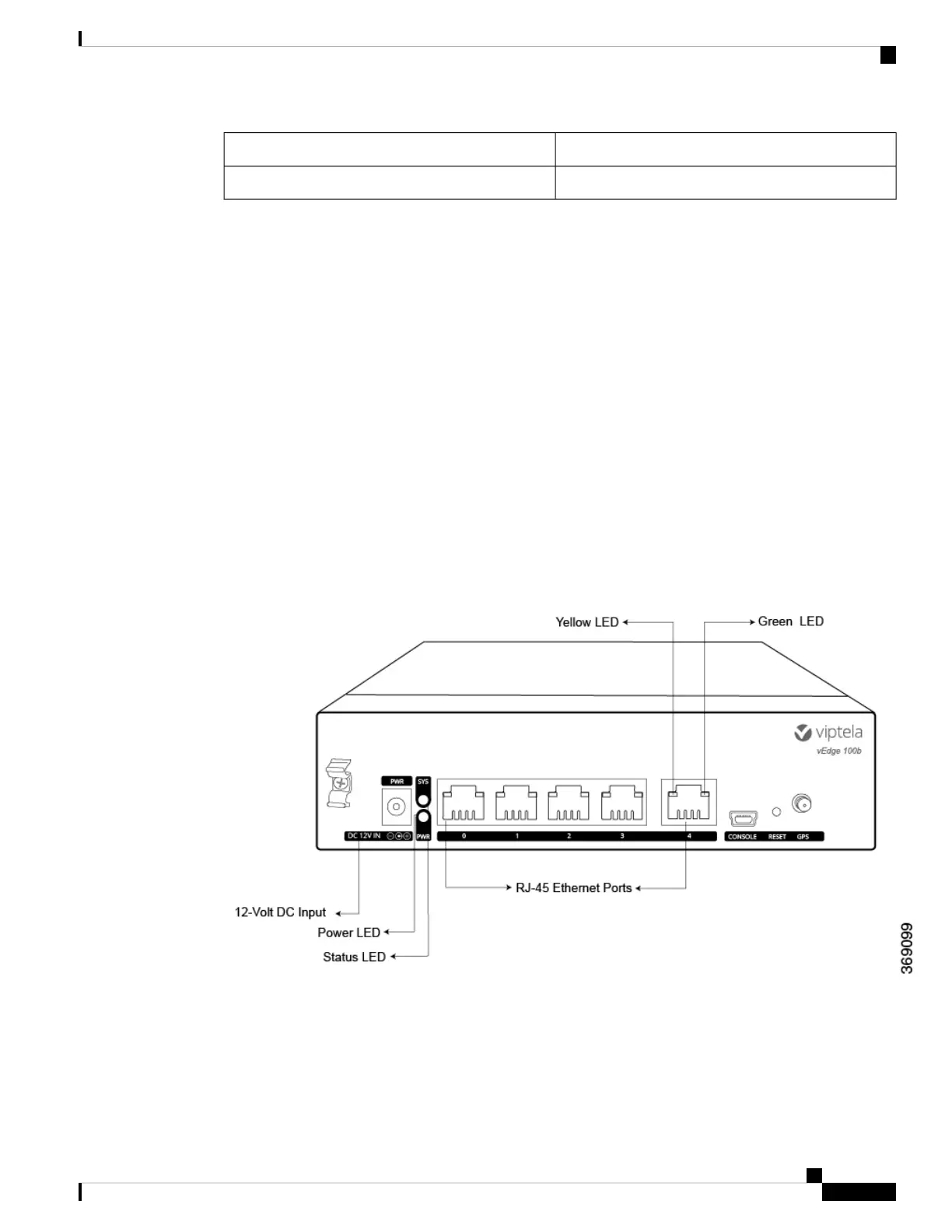
The vEdge 100b router has a power LED, a status LED, and Ethernet port LEDs located in the front panel.
Each RJ-45 port has two built-in LEDs. See Figure 1.
Figure 1: Chassis Status LEDs in a vEdge 100b Router
Table 1 describes the LEDs , their color and states, and the status they indicate.
Hardware Installation Guide for vEdge Routers
31
vEdge 100b Router
Front and Rear Panel Components
 Loading...