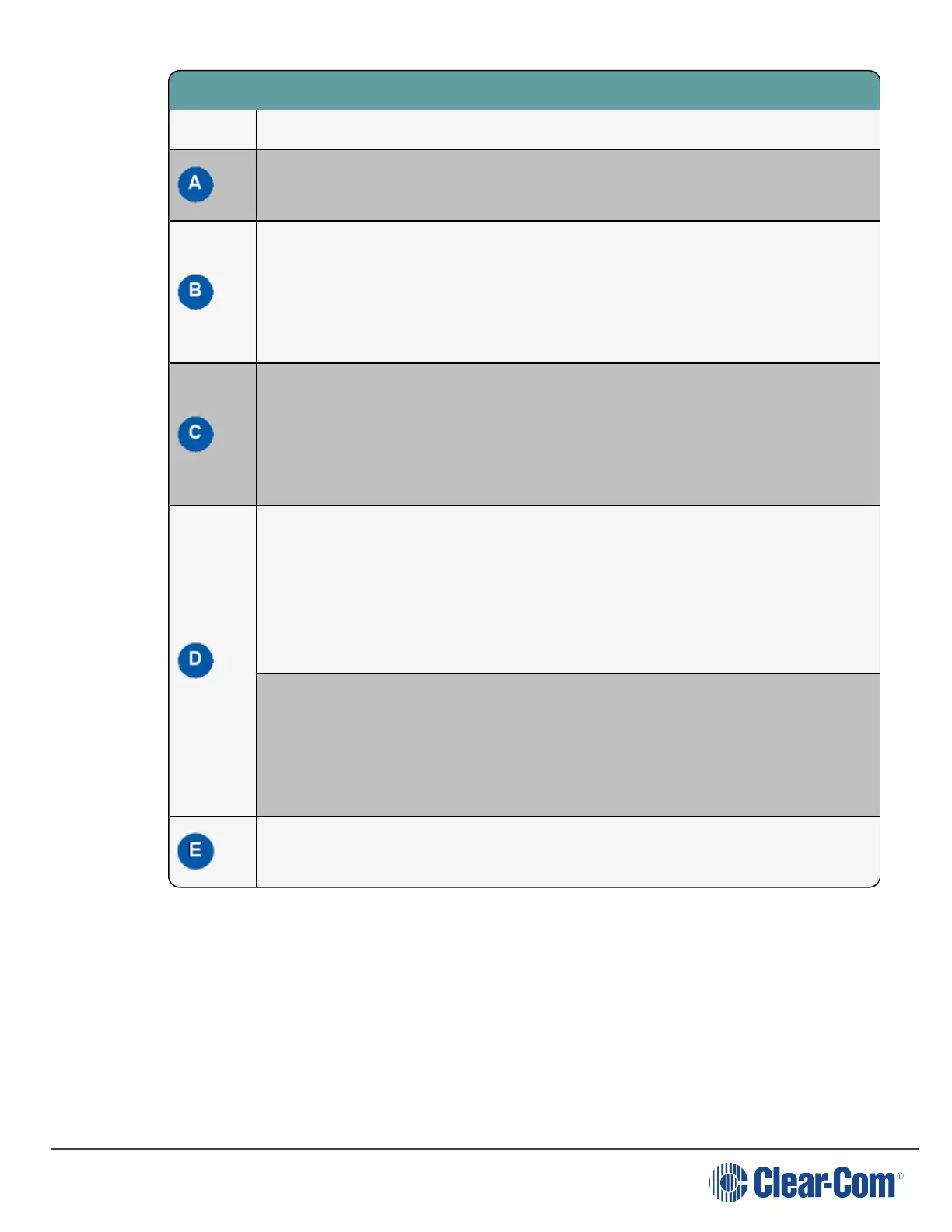
Key to transceivers
Feature Description
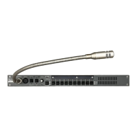
USB connector. Used to upgrade the firmware in the FS II-TA.
Matrix connector. This RJ-45/etherCON connector is used to connect the bi-
directional signal from the matrix, directly or via the splitter. Up to 800 metres
(2625 feet) of 4-pair 24AWG shielded Ethernet cable (CAT5/5e/6) can be used for
this connection between matrix and transceiver. If 26AWG cable is used the
maximum distance is 400 metres (1312 feet).
DC in power connector. This connector is used to locally power the transceiver
with the supplied universal power supply. Use of local power is required when the
transceiver is located more than 100 metres (328 feet) from the matrix or the
splitter, and is recommended even when the transceiver is closer whenever it is
available and convenient.
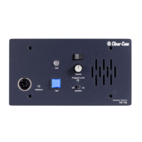
Data signal/Power LEDs. This amber LED indicates that a connection has been
established between the matrix and the transceiver, and that it is actively creating
a coverage zone within which the beltpacks can operate.
A flashing amber LED indicates that a data connection has been established with
the matrix. A solid amber light shows that there is a DECT synchronization lock
between the devices. A solid light is required for normal operation of the system.
Power LED. This LED indicates that the transceiver is receiving power, either
from its local power supply or from the connected CAT-5 cable (distances up to
100 metres, or 328 feet, from the matrix or the splitter) being powered via the FS II
Matrix.
This light is green for FSII 1.9 GHz devices and blue for FSII 2.4 GHz devices.
Mode button. The mode button is currently not in use.
card).
 Loading...