EasyManuals Logo

CleaverBrooks CFC-1000 User Manual

CleaverBrooks CFC-1000
314 pages
To Next Page IconTo Next Page
To Previous Page IconTo Previous Page
Page #22 background imageLoading...
Page #22 background image
Section 2 — Installation
2-8 Part No. 750-263
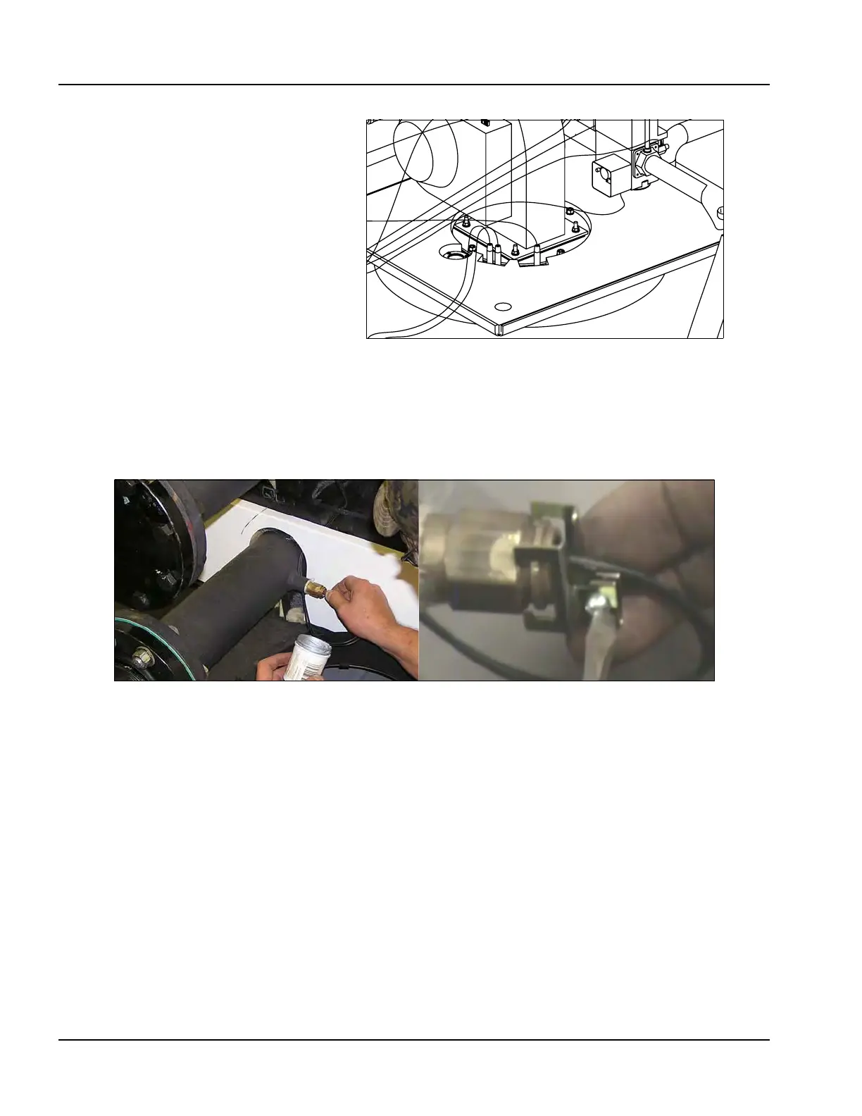
21.Route return water sensor (the 2-wire sensor) to the lower pipe on back
of boiler, and install lower panel. Coat sensor with heat-conductive
compound P/N 872-00631. Insert sensor into return pipe sensor well
and secure with mounting clamp (Figure 2-13).
22.Coat outlet feed water temperature sensor (the 3-wire sensor) with heat-
conductive compound P/N 872-00631. Insert sensor in sensor well
behind the burner (Figure 2-14).
Figure 2-12
A
B
Figure 2-13

Table of Contents

Questions and Answers:

Question and Answer IconNeed help?

Do you have a question about the CleaverBrooks CFC-1000 and is the answer not in the manual?

CleaverBrooks CFC-1000 Specifications

General IconGeneral
BrandCleaverBrooks
ModelCFC-1000
CategoryBoiler
LanguageEnglish

Related product manuals