InteliLite4 AMF20 Global Guide
613
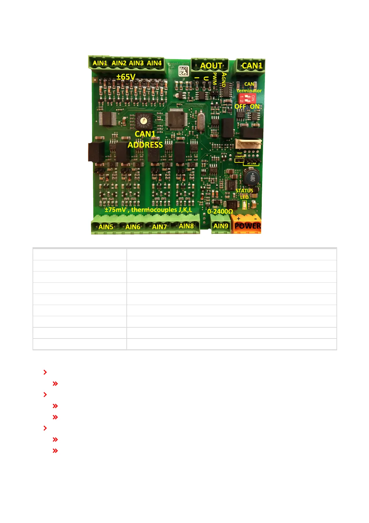
Terminals
ANALOG INPUT 9 channels
ANALOG OUTPUTS 1 channel
CAN CAN1 line
POWER Power supply
CAN LED Tx, Rx Indication transmitted or received data
Status LED LED indication of correct function
CAN terminator Terminating CAN resistor (active in position "ON")
TEST jumper Upgrade of SW
AT-LINK Connector for AT-LINK (Upgrade of SW)
Analog inputs
4 channels AIN1 – AIN4 can be configured as:
Sensor ±65V (determined for measurement of battery voltage)
4 channels AIN5 – AIN8 can be configured as:
Thermocouples – type J,K or L (in °C or °F)
Sensor ±75mV DC – (for connecting current shunts)
1 channel AIN9 can be configured as:
RTD (Pt1000, Ni1000)
Common resistance 0-2400Ω