Comau Robotics Product Instruction
36
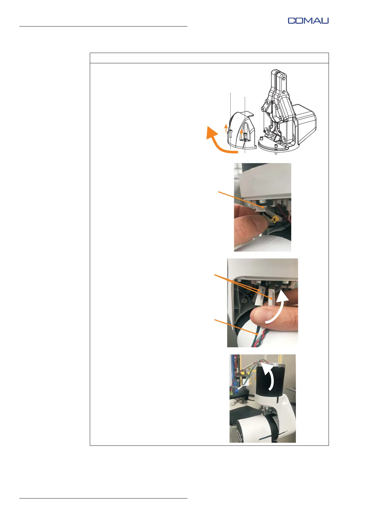
ROBOT CONFIGURATION CUSTOMIZATION
d. Using the 2.5 mm Allen wrench,
unscrew completely but without
removing (captive screws) the 2
fixing socket hex head screws
M3x10 and remove the plastic
protective cover of the e.DO
Gripper electronic board (PCB).
e. Disconnect the CAN network
terminating resistor from the
electronic board (PCB) of the
last Robot joint.
f. Insert the end with 2 connectors
(D) (CAN SUPP and CAN
SIGN) of the CAN network
connection cable and power
supply cable (E) (included with
e.DO Gripper) inside the hole of
the last Robot joint, as indicated
by the arrow in the figure.
g. Remove the two connectors
from the hole of the last Robot
joint.
Operating procedure (Continued)