ROBOT CONFIGURATION CUSTOMIZATION
37
Comau Robotics Product Instruction
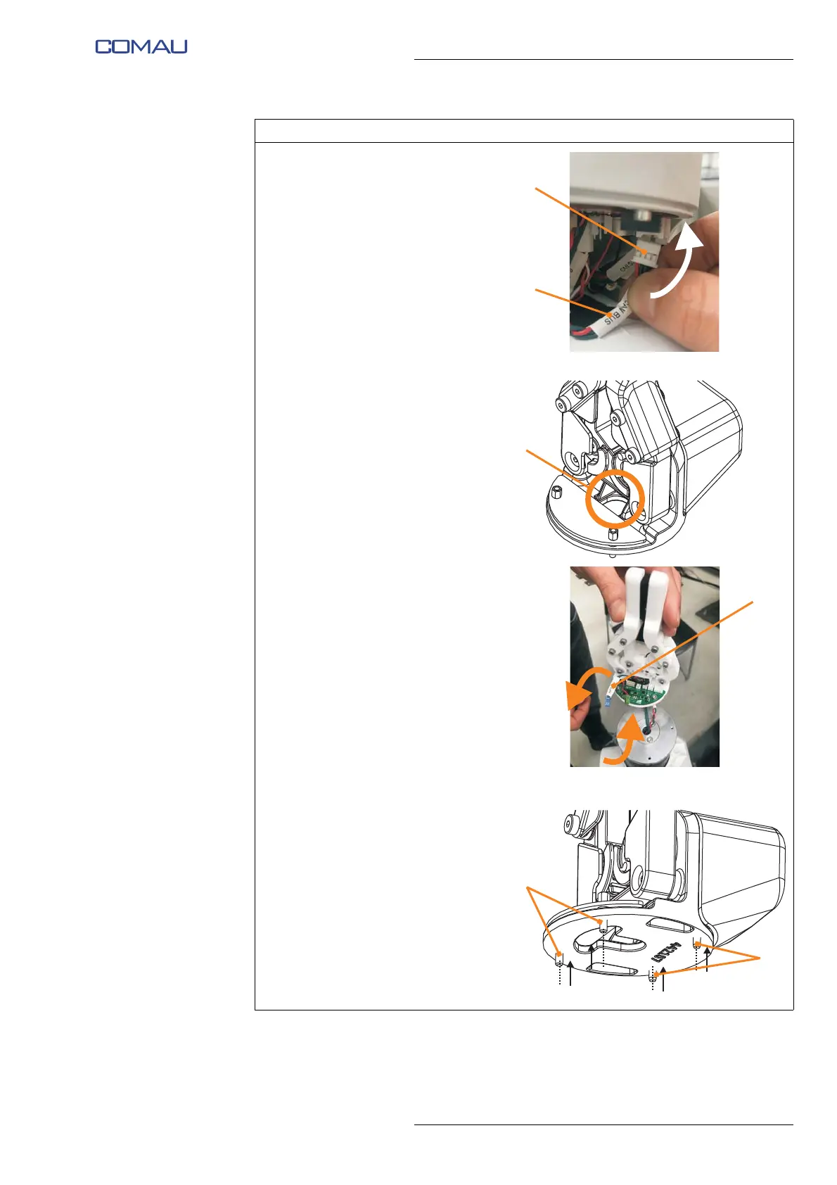
h. Connect the other end of the
CAN network connection cable
and power supply cable (E) to
the connector (F) of the last
Robot joint electronic board
(PCB) (the same connector
from which at step e. the
terminating resistor was
removed).
i. Insert the end with 2 connectors
(D) (CAN SUPP and CAN
SIGN) of the CAN network
connection cable in the hole (G)
present at the e.DO Gripper
base.
Representative figure
j. Unscrew the four screws (H) (2
socket hex head screws M3x10
on the motor side and 2 hex
spacers M3 on the electronic
board) until they are flush with
the e.DO Gripper flange.
Operating procedure (Continued)