Technical Reference Guide
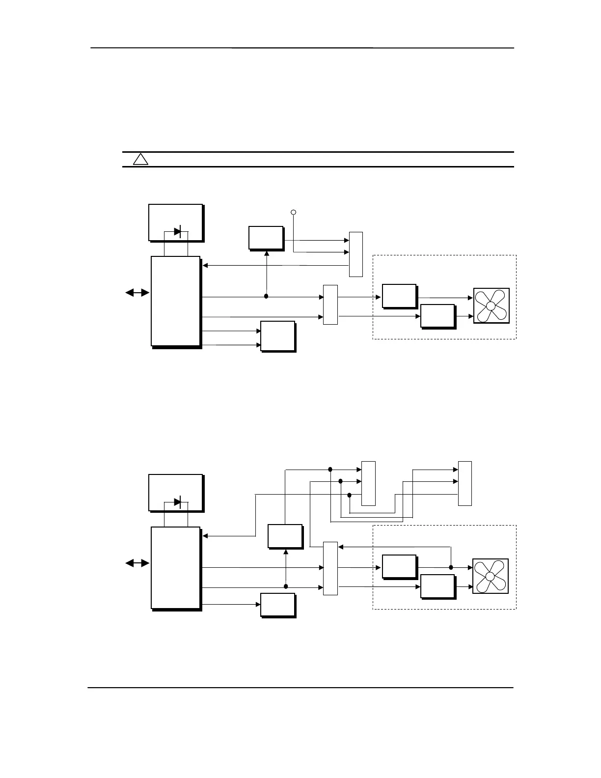
High and low thermal parameters are programmed into the ASIC by BIOS during POST. If the
high thermal parameter is reached then the fan(s) will be turned on full speed and the Therm-
signal will be asserted. The asserted Therm- signal can, with the proper software setup, be used by
the 82801 ICH2 to initiate an AOL message for transmission over a network (refer to Network
Interface Controller subsection in Chapter 5).
NOTE: These systems do not support thermister-based fans used on earlier products.
SMBus
NOTES:
PS Fan
Power Supply Assembly
P1
Speed
Control
Fan CMD
Fan Off-
(-)
(+)
On/Off
Control
Fan
Off
Fan
SPD
Processor
Sensing
ASIC
Fan
Sense
1
82801
ICH2
Therm-
10
13
Speed
Control
+12 VDC
(-)
(+)
3
2
1
Heat Sink Fan Header
P70
Interrupt
ICH2
[1] Will be +12 VDC if fan is connected.
Figure 4-11. Small Form Factor Fan Control Block Diagram
SMBus
NOTES:
Power Supply Assembly
PS Fan
P1
Speed
Control
Fan CMD
Fan Off-
Fan
Off
Fan
SPD
Processor
82801
ICH2
12
8
On/Off
Control
(+)
(-)
Fan
Sink
(+)
(-)
2
3
4
Chassis Fan
Header
24
2
3
(-)
Heat Sink Fan Header
1
(+)
On/Off
Control
Fan
Sense [1]
Sensing
ASIC
ICH2
Therm-
[1] Will be +12 VDC if chassis or boxed fan is connected and turned on.
Figure 4-12. Slim Desktop/Configurable Minitower Fan Control Block Diagram
Compaq Deskpro and Evo Personal Computers
Featuring Intel Celeron and Pentium III Processors
Fifth Edition - March 2002
4-37