Appendix I Panel Views & Descriptions
76
Features Status and Indication
Steady Green The Mode button is toggled to 100M mode.
5 100M LED
Off The Mode button is either toggled to ACT or FULL
mode.
6 POWER LED Steady Green Power supply is in normal condition.
7 Console Port A serial 9 Pin (DB9) socket is connected to PC COM Port for
monitoring the switch.
8 Reset Button By pushing the reset button once,
• The switch will clear all previous temporary error
• Switch would be re-configured with the settings stored in non-
volatile flash memory.
9 Mode Button By pressing it, you will be able to view the status of the selected mode
(Between ACT, FULL and 100M LEDs).
10 2 Open
Expansion
Module Slots
Types of Optional Module used:
• 1000Base-LX Gigabit on Fiber Module
• 1000Base-SX Gigabit on Fiber Module
• 100Base-FX Single Mode Fiber Fast Ethernet Module
• 100Base-FX Multi-Mode Fiber Fast Ethernet Module
• 1000Base-T Copper Module
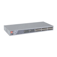
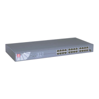
11 24 RJ45
10/100Mbps
Ports
Use UTP/STP network cables to connect
• 10 Base-T
• 100 Base-TX
All ports will detect and automatically switch to uplink mode when
connected to a switch/hub.
12 Power Socket Power input at the range of 100V - 240V AC, 50-60Hz.