7–1
Chapter 7. MAINTENANCE AND
TROUBLESHOOTING
This chapter is intended to provide procedures to assist operator and maintenance personnel in the
checkout, maintenance and troubleshooting of the CSAT. Comtech EF Data recommends that
spare replacement CSATs be used to replace CSATs removed from the system for maintenance.
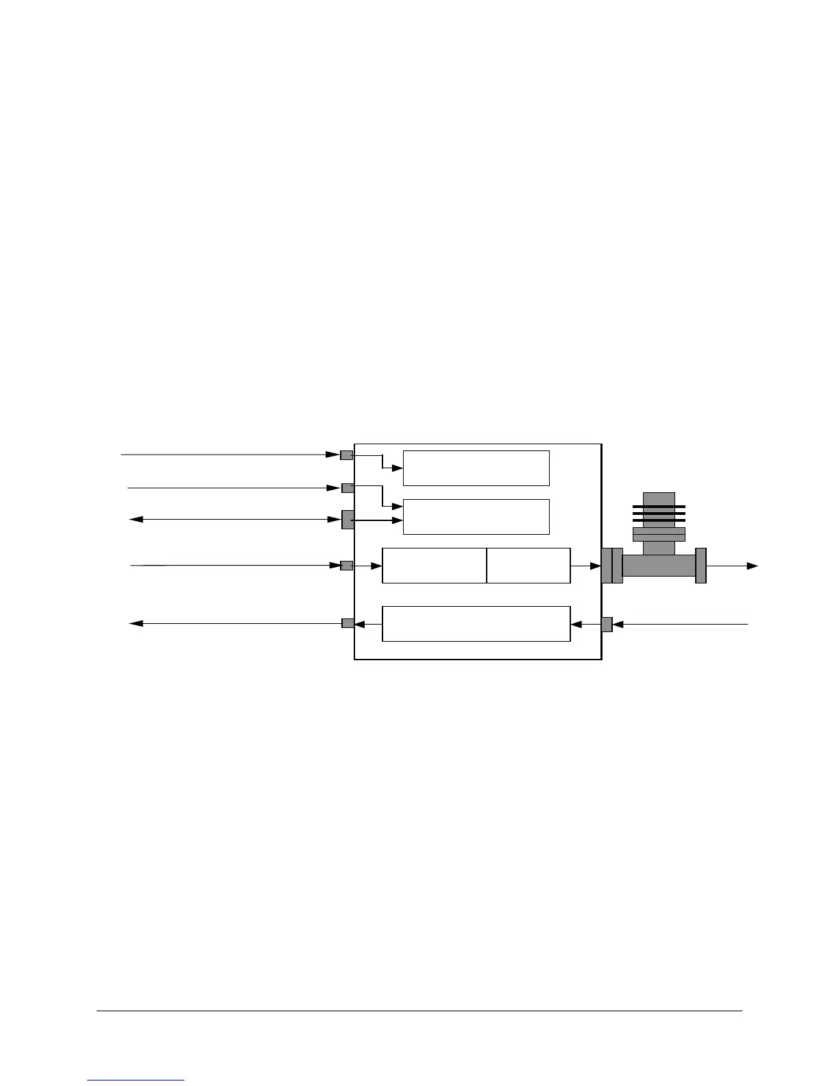
The input and output signals, the interconnecting cables and the location of the modules are as
shown in Figure 7-1.
SAT-5060/050
AC Power
Ext Ref In, 5/10 MHz
J4
J7
J5
2
J1
J6
J3
F Out,
COMM, Remote Control
x
IF IN, Tx
RF In, Rx
IF Out, Rx
SPA
PCONVERTER
OWNCONVERTER
Maintenance &
Control
ower Supply
Figure 7-1. Converter Signal and Interconnecting Cable Diagram