LPOD C-/Ku-Band Outdoor Amplifier/Block Up Converter Revision 3
System Connections, Installation, and Operation MN-LPOD
2–4
2.2.4 Connector J3 – DC Power Mains
For safety reasons, the user must note that the pin assignments for the PS-1
and PS-2 model power connections are not the same. Product damage or
personal injury may result from not properly reviewing the information in this
section.
For both the LPOD PS-1 and LPOD PS-2 models, the prime power input requirements are 38-72 VDC.
The total power required from the prime power supply depends on the model used. Please refer to
Sect. 1.5 Summary of Specifications.
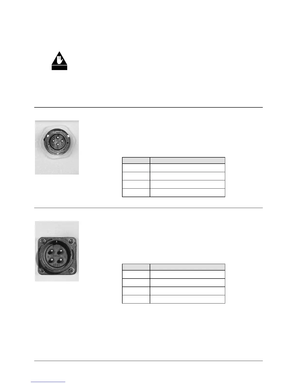
2.2.4.1 LPOD PS-1 J3 DC Power Main
The mating connector specification unique to the LPOD PS-1 DC power interface
and the pin assignments (Table 2-4) are as follows:
Mating Connector: CEFD P/N CN/STPG04F01 (
Glenair IPT06E-12-4-SSR-F7).
Table 2-4. LPOD PS-1 ‘J3 PWR IN’ Pin Assignments
Pin LPOD PS-1 Assignment
A V+
B GND
C V-
D NO CONNECT
2.2.4.2 LPOD PS-2 J3 DC Power Main
The mating connector specification unique to the LPOD PS-2 DC power
interface and the pin assignments (Table 2-5) are as follows:
Mating Connector: CEFD P/N CN/CA3106E2
222SB (ITT
Cannon CA3106E22-22SB).
Table 2-5. LPOD PS-2 ‘J3 PWR IN’ Pin Assignments
Pin LPOD PS-1 Assignment
A V+
B NO CONNECT
C NO CONNECT
D V-
WARNING