LPOD C-/Ku-Band Outdoor Amplifier/Block Up Converter Revision 3
System Connections, Installation, and Operation MN-LPOD
2–7
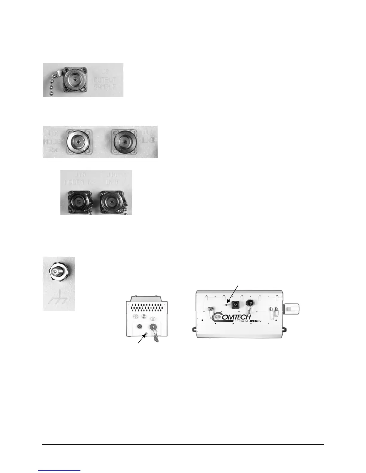
PS-1 Conns. – J10 (left), J11 (right)
PS-2 Conns. – J10 (left), J11 (right)
2.2.6 Connector J9 – Output Sample (PS-2 Only)
The Output Sample port connector is a Type ‘N’ female connector
available only on the PS-2 model. It provides a nominal -40 dB sample of
the output signal. A calibration label is provided near the connector that
shows the actual coupling values vs. frequency.
2.2.7 Connectors J10 and J11 – Optional Modem Rx and LNB Interfaces
The J10 Modem Rx and J11 LNB port connectors are both
Type ‘N’ female connectors, providing both bias and a
reference signal to a Low Noise Block Converter (LNB), and
passing the LNB’s L-Band output to the modem’s Rx input.
2.2.8 Ground Connector
A #10-32 stud is provided at the locations shown in Figure 2-2 for connecting a common
chassis ground among equipment.
Figure 2-2. LPOD Ground Connectors
PS-2 Ground location
PS-1 Ground location