LPOD C-/Ku-Band Outdoor Amplifier/Block Up Converter Revision 3
System Connections, Installation, and Operation MN-LPOD
2–2
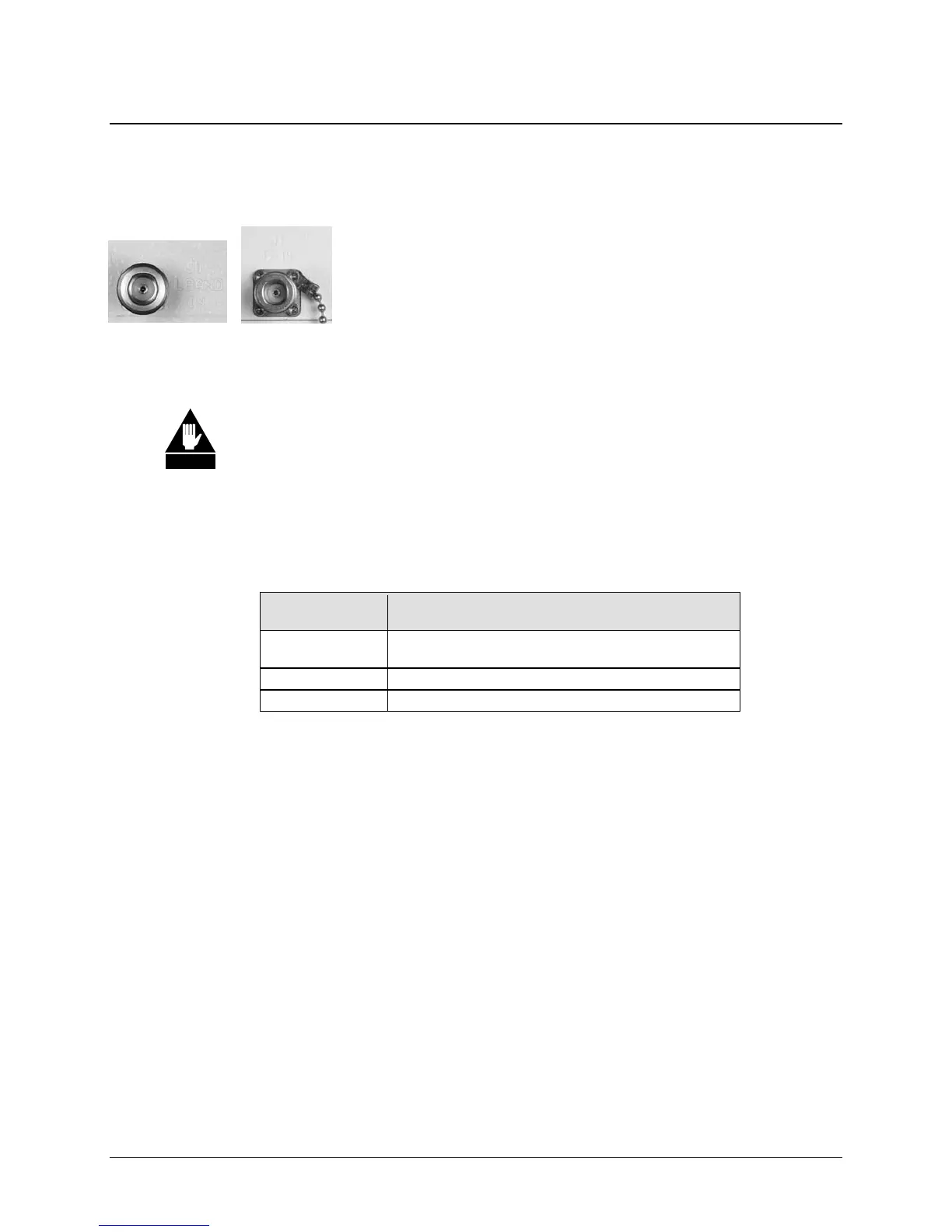
PS-1 J1 Conn.
PS-2 J1 Conn.
2.2 Interface Connectors
2.2.1 Connector J1 – RF IN
The J1 RF Input connector is a Type ‘N’ female connector. Labeled
“LBAND IN” on the LPOD PS-1 model and “TX IN” on the LPOD
PS-2 model, typical input levels (-30 dBm) depend on desired output
power and unit attenuation. To prevent damage to the LPOD, RF input
levels should not exceed +15 dBm.
2.2.2 Connector J2 – RF OUT
For safety reasons, never look directly into the waveguide output.
The J2 RF Out connector may be a waveguide or coaxial interface, as shown in Figure 2-1. The
type of interface used depends on the LPOD model and/or frequency range of the unit, as
described in Table 2-1.
Table 2-1. J2 RF Outpu
t
Unit
Frequency Band
Output
(typical for PS-1 or PS-2 unless noted otherwise)
C
PS-1: Type ‘N’ Coax Output
PS-2: CPR137G Waveguide Flange
X CPR112G Waveguide Flange
Ku WR75G Waveguide Flange
WARNING