2–1
Chapter 2. SYSTEM
CONNECTIONS, INSTALLATION
and OPERATION
2.1 Overview
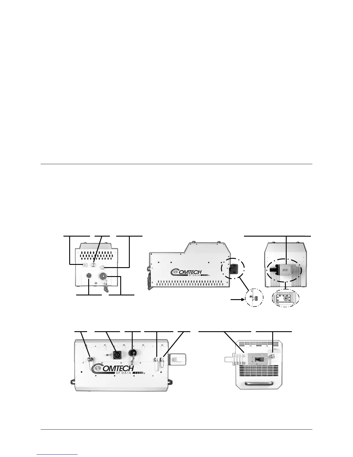
This chapter summarizes the connectors provided for all necessary external connections between the
LPOD PS-1 (Figure 2-1 TOP) or PS-2
(Figure 2-1 BOTTOM) units and other equipment. Basic
installation and operational information is also provided in Sect.2.3. For a detailed overview on the
LPOD’s operability (via remote M&C commands/queries), refer to Appendix B. REMOTE
CONTROL.
Figure 2-1. LPOD Connectors
(TOP: PS-1 model; BOTTOM: PS-2 model)
J1 J3 J6 J10 J11 J2 RF Out J9
Tx In Power In COM1 Modem Rx LNB (Waveguide Output) Output Sample
Power In COM1 J2 RF Out
C-Band shown
J3 J6 (Coax Output)
J10 J11 J1 J2 RF Out
Ku-Band shown
Modem Rx LNB L-Band In (Waveguide Output)