-
-
-
- 94 -
-
-
-
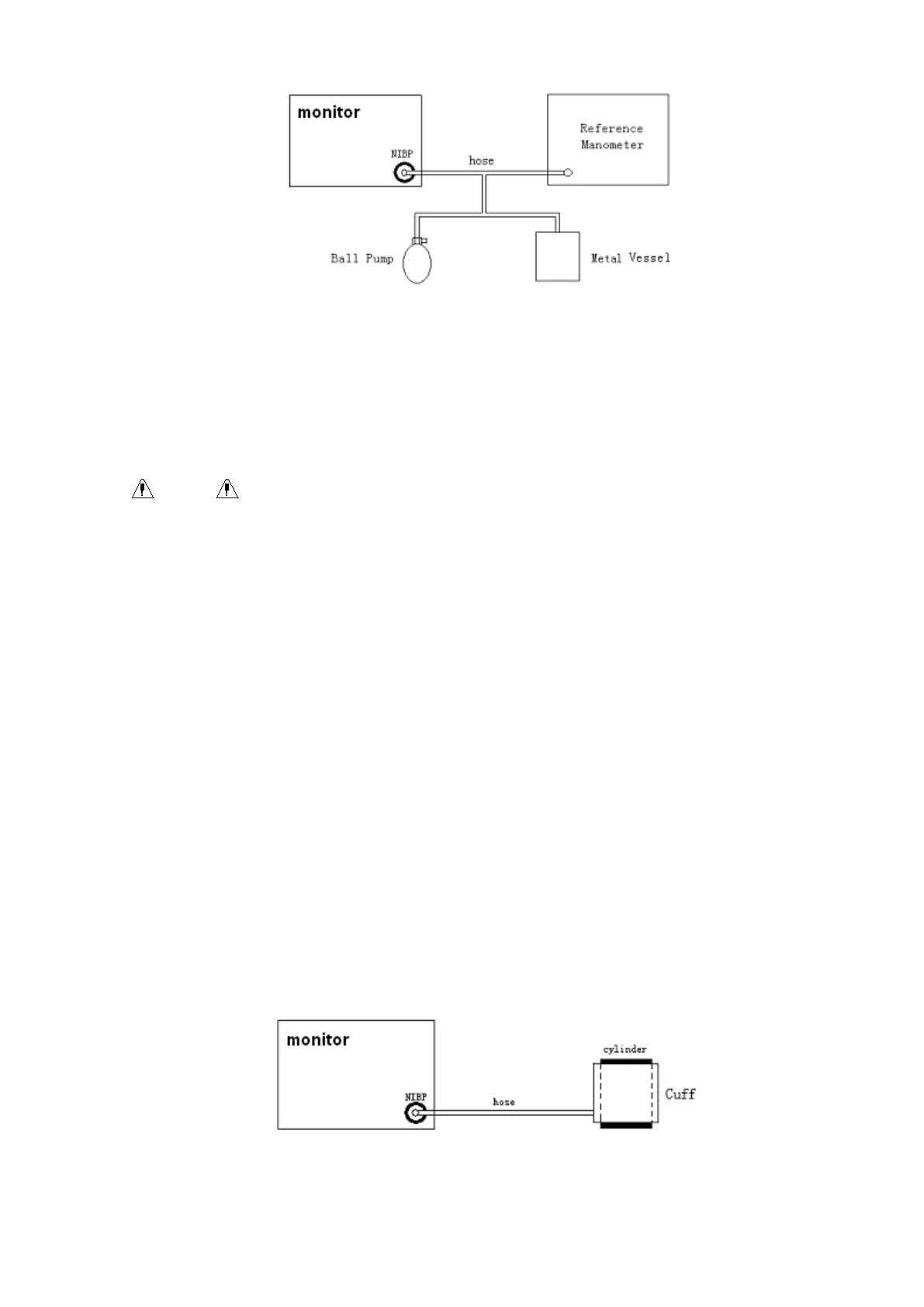
Figure 13 - 3 Diagram of NIBP calibration
■ PNEUMATIC
This item is used for air leakage test. Turn the knob to pick the item to start the air leakage test.
Then the item will change into STOP PENUM, which if picked, the system will stop air leakage
test.
Warning
Warning
Warning
Warning
This
This
This
This pneumatic
pneumatic
pneumatic
pneumatic test
test
test
test other
other
other
other than
than
than
than being
being
being
being specified
specified
specified
specified in
in
in
in the
the
the
the EN
EN
EN
EN 1060-1
1060-1
1060-1
1060-1 standard
standard
standard
standard is
is
is
is to
to
to
to be
be
be
be used
used
used
used by
by
by
by the
the
the
the
user
user
user
user to
to
to
to simply
simply
simply
simply determine
determine
determine
determine whether
whether
whether
whether there
there
there
there are
are
are
are air
air
air
air leaks
leaks
leaks
leaks in
in
in
in the
the
the
the NIBP
NIBP
NIBP
NIBP airway.
airway.
airway.
airway. If
If
If
If at
at
at
at the
the
the
the end
end
end
end of
of
of
of the
the
the
the test
test
test
test
the
the
the
the system
system
system
system gives
gives
gives
gives the
the
the
the prompt
prompt
prompt
prompt that
that
that
that the
the
the
the NIBP
NIBP
NIBP
NIBP airway
airway
airway
airway has
has
has
has air
air
air
air leaks,
leaks,
leaks,
leaks, please
please
please
please contact
contact
contact
contact the
the
the
the manufacturer
manufacturer
manufacturer
manufacturer
for
for
for
for repair.
repair.
repair.
repair.
Procedure
Procedure
Procedure
Procedure of
of
of
of the
the
the
the a
a
a
a ir
ir
ir
ir l
l
l
l eakage
eakage
eakage
eakage test:
test:
test:
test:
1) Connect the cuff securely with the socket for NIBP air hole.
2) Wrap the cuff around the cylinder of an appropriate size.
3) Access the NIBP SETUP menu.
4) Turn the knob to the PNEUMATIC item and press the knob. Then the prompt “ Pneum testing …”
will appear on the bottom of the NIBP parameter area indicating that the system has started
performing pneumatic test.
5) The system will automatically Inflate the pneumatic system to about 180mmHg.
6) After 20 seconds or so, the system will automatically open the deflating valve, which marks the
completion of a pneumatic measurement.
7) If no prompt appears on the bottom of the NIBP parameter area, it indicates that the airway is in
good situation and no air leaks exist. However if the prompt “ PNEUMATIC LEAK ” appears in the
place, it indicates that the airway may have air leaks. In this case, the user should check for
loose connection. After confirming secure connections, the user should re-perform the
pneumatic test. If the failure prompt still appears, please contact the manufacturer for repair.
Figure
Figure
Figure
Figure 13-
13-
13-
13- 4
4
4
4 Diagram
Diagram
Diagram
Diagram of
of
of
of NIBP
NIBP
NIBP
NIBP air
air
air
air leakage
leakage
leakage
leakage test
test
test
test