5. Each Component Function
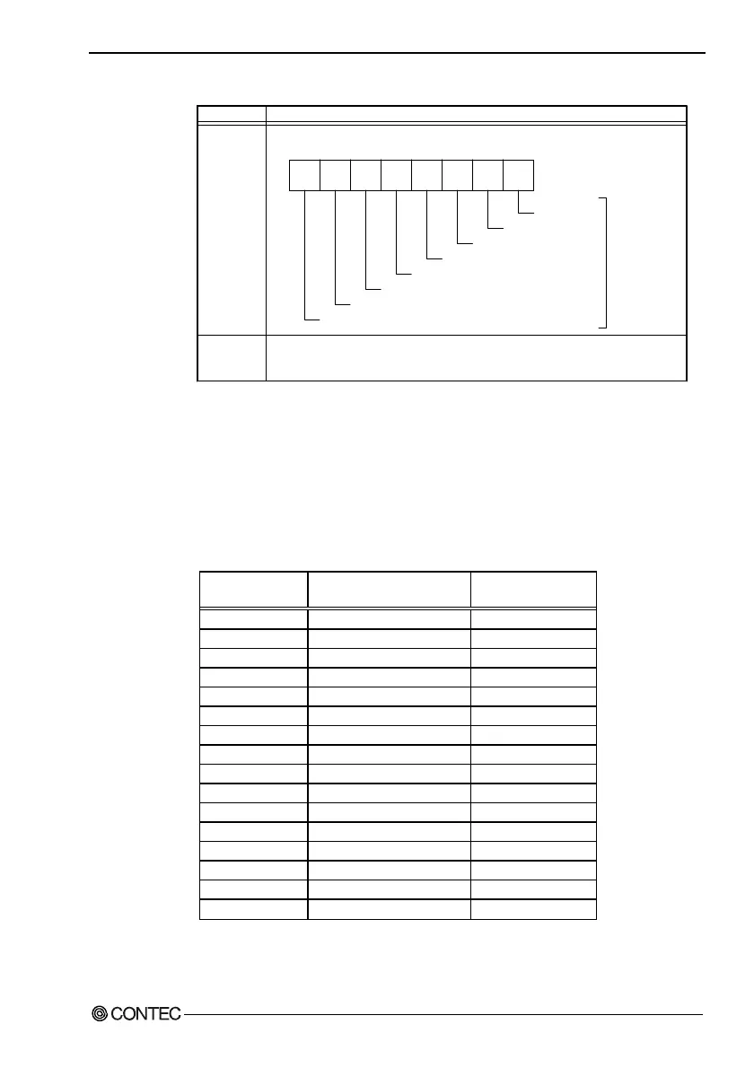
Table 5.10. Function of Each Register < 4 / 4 >
MSR : Modem Status Register
D7 D6 D5 D4 D3 D2 D1 D0
03FEH
I/O address Description
SCR : Scratchpad Register
03FFH
DCD RI DSR CTS
DDCD
TERI
DDSR
DCTS
Delta CTS
Delta DSR
Trailing edge RI
Delta data carrier detect
CTS
DSR
RI
DCD
This is an 8-bit, readable/writable register which is available to the user to
allow data to be saved temporarily.
Since these
statuses are
not used with
RS-485, data
is not valid.
Baud Rate Settings
A baud rate is set by software by dividing the clock input
(1.8432MHz). The baud rate in terms of hardware can be set to a
maximum of 115,200 bps. The baud rates available in practice
depend on the operating environment (cable, software, etc.). The
table below lists typical baud rates and their respective values to be
written to the divisor latch register (LSB, MSB).
Table 5.11. Baud Rate Settings
Baud rate to be set
Value to be set
in the divisor register
Setting error (%)
50 2304 ---
75 1536 ---
110 1047 0.026
134.5 857 0.058
150 768 ---
300 384 ---
600 192 ---
1200 96 ---
1800 64 ---
2000 58 0.69
2400 48 ---
3600 32 ---
4800 24 ---
7200 16 ---
9600 12 ---
19200 6 ---
Example: To set 9,600 bps, write "00" to the (MSB) divisor latch
register and "12 (decimal)" to the (LSB) divisor latch register.
User’s Manual
57