5. Each Component Function
Printer Port Interface
A printer port is provided. You can use BIOS Setup to configure an
operation mode, I/O address, interrupt, DMA channel and unused
state for this port.
The connector is named PRINTER.
Table 5.18. Printer Ports and I/O Addresses
I/O address Interrupt
3BCh - 3BFh
378h - 37Fh
278h - 27Fh
IRQ 5
IRQ 7
The BIOS defaults to the following factory settings:
Parallel port: ECP,378h~37Fh,IRQ7,DMA3,
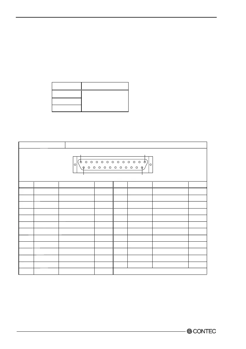
Table 5.19. Printer Port Connector
Pin No.
1
2
3
4
5
6
7
8
9
10
11
12
13
Connector used on the unit
Signal
-STRB
D 0
D 1
D 2
D 3
D 4
D 5
D 6
D 7
-ACK
BUSY
PE
SELECT
Meaning
Enable data
Data bit 0
Data bit 1
Data bit 2
Data bit 3
Data bit 4
Data bit 5
Data bit 6
Data bit 7
Ready to accept data
Busy
Out of paper
Select state
Direction
Output
Output
Output
Output
Output
Output
Output
Output
Output
Input
Input
Input
Input
25pin D-SUB (FEMALE)
Fastening screw: No. 4-40 UNC inch thread
Pin No.
14
15
16
17
18
19
20
21
22
23
24
25
Signal
-AFEED
-ERROR
-INIT
-SELECT*IN
GND
GND
GND
GND
GND
GND
GND
GND
Meaning
Automatic feed
Not available
Initialize
Input allowed
Ground
Ground
Ground
Ground
Ground
Ground
Ground
Ground
Direction
Output
Input
Output
Output
-----
-----
-----
-----
-----
-----
-----
-----
13
1
1425
-----
64
User’s Manual