5. Each Component Function
Floppy Disk Interface
The PANECON-PC is equipped with a FD controller to allow one
FD drive to be connected to the FD connector named FD on the front
end. Use the FD drive that is available as a dedicated option.
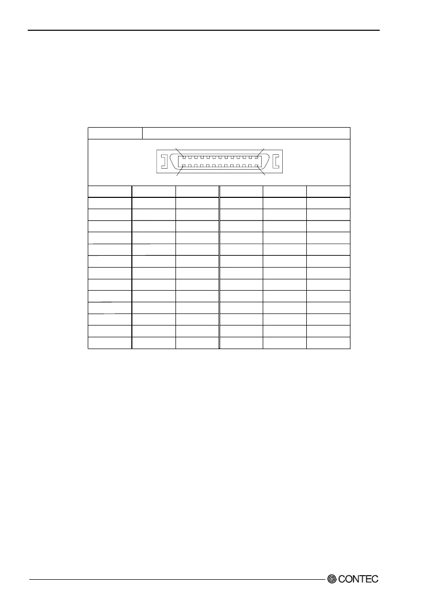
Table 5.12. FD Connector
Connector in use
Pin No.
1
3
5
7
9
11
13
15
17
19
21
23
25
Signal
HDSEL
RDATA
GND
GND
GND
WDATA
DENSEL
DENSEL
N.C.
DRV_SEL
+5V
+5V
INDEX
Direction
Output
Input
-----
-----
-----
Output
Output
Output
-----
Output
-----
-----
Input
Pin No.
2
4
6
8
10
12
14
16
18
20
22
24
26
Signal
WRTPRT
TRK0
GND
WGATE
GND
GND
STEP
DIR
MTR_ON
N.C.
DSKCHG
N.C.
+5V
Direction
Input
Input
-----
Output
-----
-----
Output
Output
Output
-----
Input
-----
-----
26-socket, half-pitch connector, Equivalent to the DX10G1M-26SE
226
25 1
Compatible Connector on the Cable Side
Plug connector : AMP, P/N
1756774-4 (AWG#28 for pressure welding)
Shield case kit : AMP, P/N 1756774-4
or
Plug connector : 3M, P/N
10126-6000EL (AWG#28 for pressure welding)
Shell : 3M, P/N 10326-3210-000
or
Plug connector : 3M, P/N 10126-3000VE
(AWG#24 - #30 provided with solder)
Shell system : 3M, P/N 10326-52F0-008 (Non-shield shell kit)
Cable Length
Use within a maximum cable length of 60cm.
58
User’s Manual