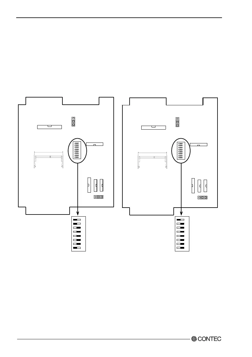
3. Hardware Setup
Locations and Settings of Internal Connectors and
Jumpers
When you remove the top cover and hard disk bracket, the
connectors, jumpers, and switches are laid out as shown in the figure
below:
IPC-PT/L630S(PCI)C, IPC-PT/H630X(PCI)C,
IPC-PT/L630S(PCI)CP IPC-PT/H630X(PCI)CP
JP3
123
654321
ON
S1
87
M1
JP1
12
3
CN20
CN19 SERIAL3
CN16 SERIAL4
CN14
CN6
JP3
123
654321
ON
S1
87
M1
JP1
123
CN20
CN19 SERIAL3
CN16 SERIAL4
CN14
CN6
654321
ON
OFF
S1
87
654321
ON
OFF
S1
87
Figure 3.3. Locations and Settings of Jumpers, Connectors,
and Switches inside the Top Cover
(IPC-PT/L630S(PCI)C,
IPC-PT/L630S(PCI)CP,
IPC-PT/H630X(PCI)C,
IPC-PT/H630X(PCI)CP)
20
User’s Manual