120 Epsilon EP-P Drive Reference Manual
www.controltechniques.com Revision: A4
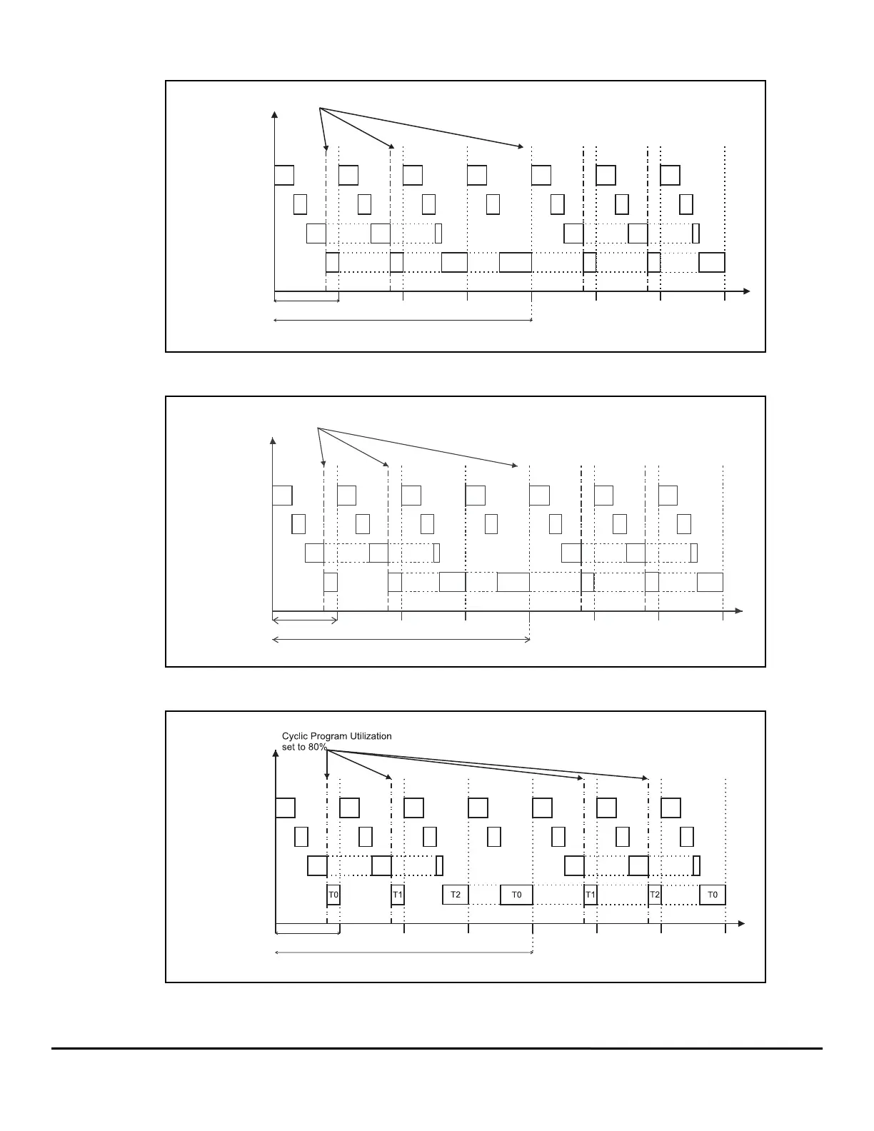
The following three figures show how the drive processes Real Time, Cyclic, and User Programs with different number of tasks.
Figure 136: Diagram of User Program, a Real Time Program and a Cyclic Program
Figure 137: Diagram of User Program on Two Tasks, a Real Time Program and a Cyclic Program
Figure 138: Diagram of User Programs on Three Tasks, a Real Time Program and a Cyclic Program
T0
Control Loop
Cyclic Program
Update Rate
User Program
T0
T0
Cyclic Update = 4x Update Rate
Control Loop + Real Time + Cyclic + User Program on one Task.
Cyclic Program Update Rate set to 4x Trajectory Update Rate and
Utilization set to 80%.
Cyclic Program Utilization
set to 80%
Real Time Program
T0 T0
T0
T0
T0
Update Rate
Cyclic Update = 4x Update Rate
Control Loop + Real Time + Cyclic + User Programs on two Tasks.
Cyclic Program Update Rate set to 4x Trajectory Update Rate and
Utilization set to 80%.
Cyclic Program Utilization
set to 80%
T1 T0 T1 T0 T1 T0
Control Loop
Cyclic Program
User Program
Real Time Program
Real Time Program
Control Loop
Control Loop + Real Time + User Programs on three Tasks.
Cyclic Program fUpdate Rate set to 4x Trajectory Update Rate and
Utilization set to 80%.
Cyclic Program
User Program
Cyclic Update = 4x Update Rate
Update Rate