84 Epsilon EP-P Drive Reference Manual
www.controltechniques.com Revision: A4
Therefore, Selector.Selection3 would activate.
The Selector.Select lines can change without any action until the Selector.SelectorInitiate destination is activated.
Selector.Selection sources can be tied to any destination in the Assignments view. Figure 96 shows the four selection lines being tied to Index
0 through Index 3 initiates. By doing this, we could initiate up to four indexes with only two select lines and a selector initiate. This can help
minimize the number of inputs required to initiate a large number of indexes or programs.
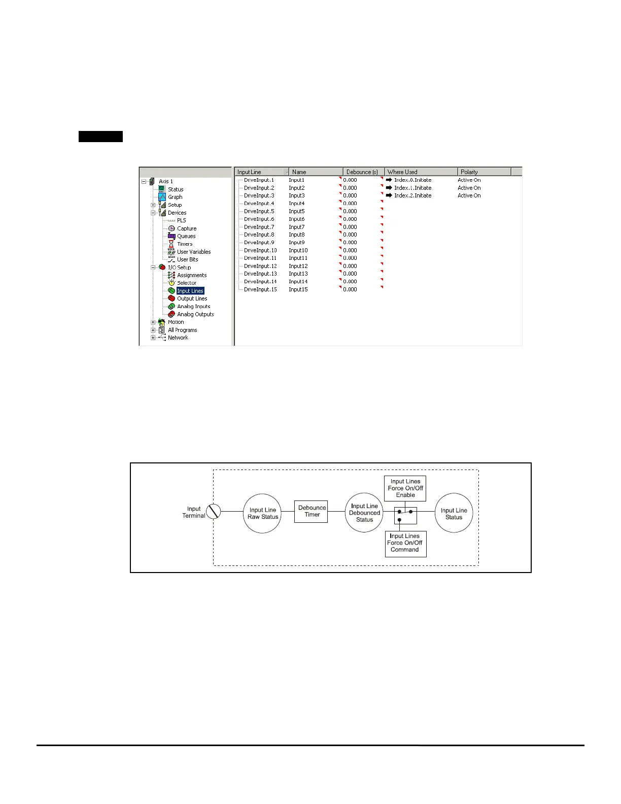
3.29 Input Lines View
The Input Lines View displays any functions that have been assigned to the drive hardware inputs. See Figure 97.
No assignments can be made using the Input Lines View, assignments are only displayed in the Input Lines View.
Figure 97: Input Lines View
The following two functions can be performed on the Input Lines view.
Name
You can assign a descriptive name to each input and make the setup easier to follow. The length of the text string is limited to a maximum of
12 characters. Simply double click on the Name field of any input line to assign a name to it.
Debounce
You can program a “Debounce Time” to any input line, which means the motion profile will need to be steady for at least the debounce time
before it is recognized. This feature helps prevent false triggering in applications in noisy electrical environments. At the end of the debounce
time, the next action can occur.
Figure 98: Input Line Diagram
If the Input Line attached to the home sensor is debounced, the actual rising edge of the Home Sensor is used to determine the Home
Reference Position (the debounce time ensures a minimum pulse width).
3.30 Output Lines View
The Output Lines View displays any functions that have been assigned to the drive hardware outputs. See Figure 99.