Parameter
structure
Keypad and
display
Parameter x.00
Parameter description
format
Advanced parameter
descriptions
Serial comms
protocol
Performance
Menu 6
Mentor MP Advanced User Guide 105
Issue Number: 4 www.controltechniques.com
The drive event flags indicate certain actions have occurred within the drive as described below.
Defaults loaded (Bit 0)
The drive sets bit 0 when defaults have been loaded and the associated parameter save has been completed. The drive does not reset this flag
except at power-up. This flag is intended to be used by SM-Applications Solutions Module programs to determine when the default loading process is
complete. For example an application may require defaults that are different from the standard drive defaults. These may be loaded and another
parameter save initiated by the SM-Applications module when this flag is set. The flag should then be cleared so that the next event can be detected.
Pr 6.42 and Pr 6.43 provide a method of controlling the sequencer inputs and other functions directly from a single control word. If Pr 6.43 = 0 the
control word has no effect, if Pr 6.43 = 1 the control word is enabled. Each bit of the control word corresponds to a sequencing bit or function as
shown below.
Bits 0-7 and bit 9: sequencing control
When the control word is enabled (Pr 6.43 = 1), and the Auto/manual bit (bit7) are both one, bits 0 to 6 and bit 9 of the control word become active.
The equivalent parameters are not modified by these bits, but become inactive when the equivalent bits in the control word are active. When the bits
are active they replace the functions of the equivalent parameters. For example, if Pr 6.43 = 1 and bit 7 of Pr 6.42 = 1 the drive enable is no longer
controlled by Pr 6.15, but by bit 0 of the control word. If either Pr 6.43 = 0, or bit 7 of Pr 6.42 = 0, the drive enable is controlled by Pr 6.15.
Bit 8: Analog/preset reference
When the control word is enabled (Pr 6.43) bit 8 of the control word becomes active. (Bit 7 of the control word has no effect on this function.) The state
of bit 8 is written to Pr 1.42. With default drive settings this selects analog reference 1 (bit8 = 0) or preset reference 1 (bit8 = 1). If any other drive
parameters are routed to Pr 1.42 the value of Pr 1.42 is undefined.
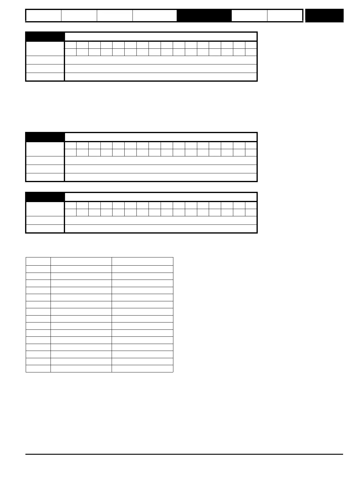
6.41 Drive event flags
Coding
Bit SP FI DE Txt VM DP ND RA NC NV PT US RW BU PS
111
Range 0 to 65535
Default 0
Update rate Background write
6.42 Control word
Coding
Bit SP FI DE Txt VM DP ND RA NC NV PT US RW BU PS
111
Range 0 to 32,767
Default 0
Update rate Bits 0 –7: 4 ms read, Bits 8-15: Background read
6.43 Control word enable
Coding
Bit SP FI DE Txt VM DP ND RA NC NV PT US RW BU PS
111
Default 0
Update rate Related to bits 0-7: 4 ms read, related to bits 8-15: Background read
Bit Function Equivalent parameter
0 Drive enable Pr 6.15
1 Run forward Pr 6.30
2Jog Pr 6.31
3 Run reverse Pr 6.32
4 Forward/reverse Pr 6.33
5Run Pr 6.34
6 Not stop Pr 6.39
7 Auto/manual
8 Analog/Preset reference Pr 1.42
9 Jog reverse Pr 6.37
10 Reserved
11 Reserved
12 Trip drive
13 Reset drive Pr 10.33
14 Keypad watchdog