Menu 6
Parameter
structure
Keypad and
display
Parameter x.00
Parameter description
format
Advanced parameter
descriptions
Serial comms
protocol
Performance
106 Mentor MP Advanced User Guide
www.controltechniques.com Issue Number: 4
Bit12: Trip drive
When the control word is enabled (Pr 6.43) bit 12 of the control word becomes active. (Bit 7 of the control word has no effect on this function.) When
bit 12 is set to one a CL.bit trip is initiated. The trip cannot be cleared until the bit is set to zero
Bit 13: Reset drive
When the control word is enabled (Pr 6.43) bit 13 of the control word becomes active. (Bit 7 of the control word has no effect on this function.) When
bit 13 is changed from 0 to 1 the drive is reset. This bit does not modify the equivalent parameter (Pr 10.33).
Bit 14: Keypad watchdog
When the control word is enabled (Pr 6.43) bit 14 of the control word becomes active. (Bit 7 of the control word has no effect on this function.) A
watchdog is provided for an external keypad or other device where a break in the communication link must be detected. The watchdog system can be
enabled and/or serviced if bit 14 of the control word is changed from zero to one with the control word enabled. Once the watchdog is enabled it must
be serviced at least once every second or an "SCL" trip occurs. The watchdog is disabled when an "SCL" trip occurs, and so it must be re-enabled
when the trip is reset.
The drive thermal model system normally controls the fan speed, however the fan can be forced to operate at full speed if this parameter is set to 1.
When this is set to 1 the fan remains at full speed until 10 s after this parameter is set to zero.
Note when the drive is in the UU state, the fan always runs at minimum speed.
The drive comms system 128 bytes buffer used with ANSI or Modbus rtu protocols via the 485 connector can be controlled by a Solutions Module
under certain circumstances. This parameter shows which node has control of the buffer (0 (drv) = drive, 1 (Slot1) = Solutions Module in slot 1, etc. If
a Solutions Module has control of the buffer the drive will use an alternative buffer for 485 comms and the following restrictions will apply:
1. Comms messages via the 485 port are limited to a maximum of 32 bytes
2. The 6 pin keypad port will operate correctly with an LED keypad, but it will no longer operate with an LCD keypad
3. Modbus messages using the CMP protocol can only route messages to nodes within the drive. It will not be possible for these to be routed further,
i.e. via CT Net on an SM Applications module.
When this parameter is 1 the reference has to be below 0.8 % of full speed before the sequencer can go to the run state.
When using the contactor logic the run command has to be delayed to allow time for the contactor to change before allowing the firing pulses.
This parameter can be used to control an external contactor.
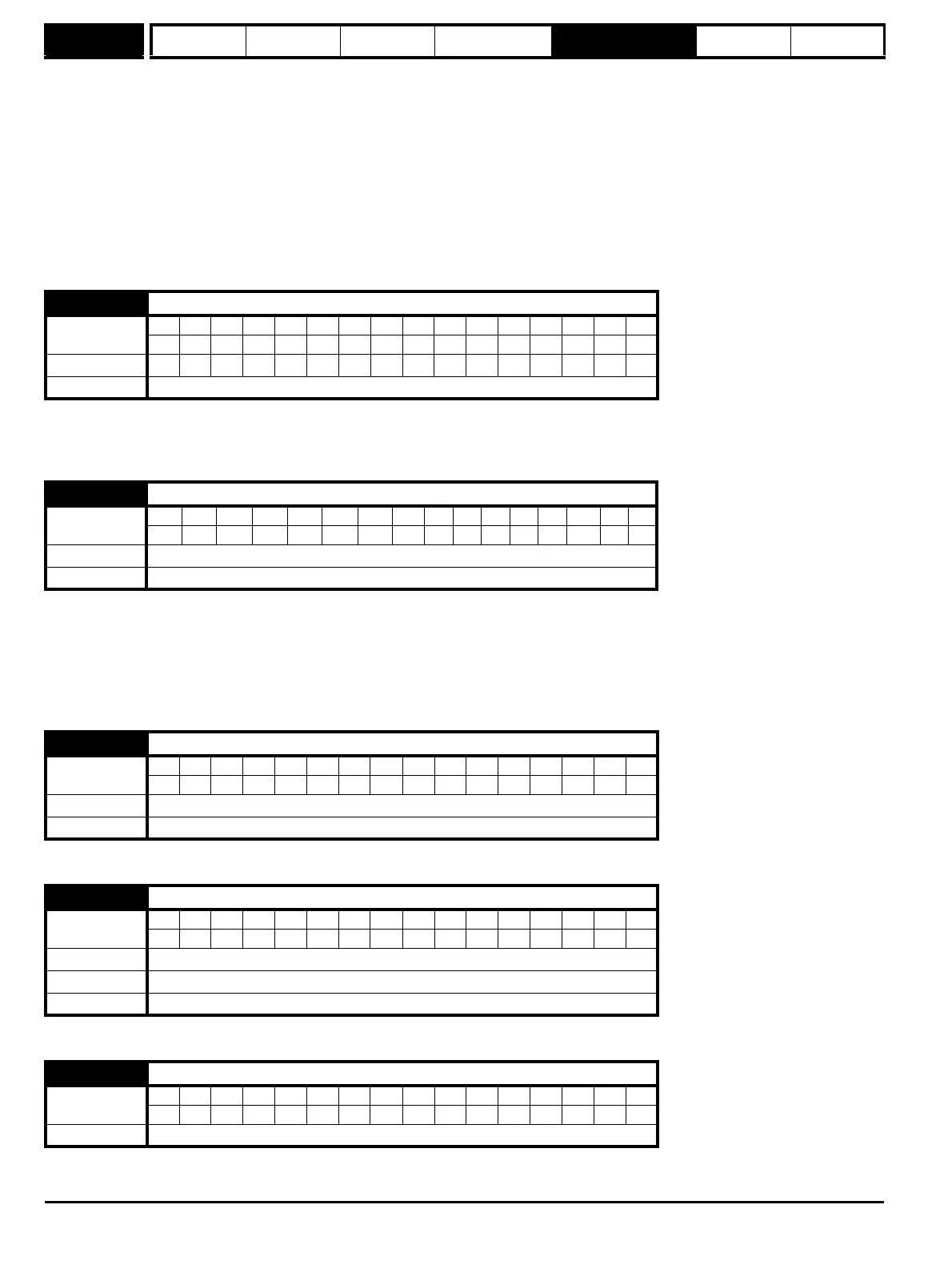
6.45 Force cooling fan to run at full speed
Coding
Bit SP FI DE Txt VM DP ND RA NC NV PT US RW BU PS
111
Default 0
Update rate Background read
6.50 Drive comms state
Coding
Bit SP FI DE Txt VM DP ND RA NC NV PT US RW BU PS
11111
Default 0 to 3
Update rate Background write
6.52 Zero reference interlock
Coding
Bit SP FI DE Txt VM DP ND RA NC NV PT US RW BU PS
111
Default 0
Update rate Background read
6.54 Run rising edge delay
Coding
Bit SP FI DE Txt VM DP ND RA NC NV PT US RW BU PS
111
Range 0 to 25.0 s
Default 0.3
Update rate Background read
6.55 Contactor active
Coding
Bit SP FI DE Txt VM DP ND RA NC NV PT US RW BU PS
1111
Update rate Background write