Menu 12
Parameter
structure
Keypad and
display
Parameter x.00
Parameter description
format
Advanced parameter
descriptions
Serial comms
protocol
Performance
164 Mentor MP Advanced User Guide
www.controltechniques.com Issue Number: 4
The variable selectors allow two source values (defined by Pr 12.08, Pr 12.28 and Pr 12.09, Pr 12.29) to be combined as defined by the mode
(Pr 12.10, Pr 12.30) to produce an output (Pr 12.12, Pr 12.32) which can be routed to the destination parameter (defined by Pr 12.11, Pr 12.31). The
actions of the variable selector are defined by the mode parameter as given below. If the mode parameter is changed or the variable selector is
disabled because neither source is routed to a valid parameter all the internal state variables (i.e. filter accumulator, etc.) within the selector are reset.
When the Sectional control mode is selected the function is also reset, and the output is held at zero, when the control (Pr 12.15 or Pr 12.35) is zero.
It is active when the control has a non-zero value.
Sectional control
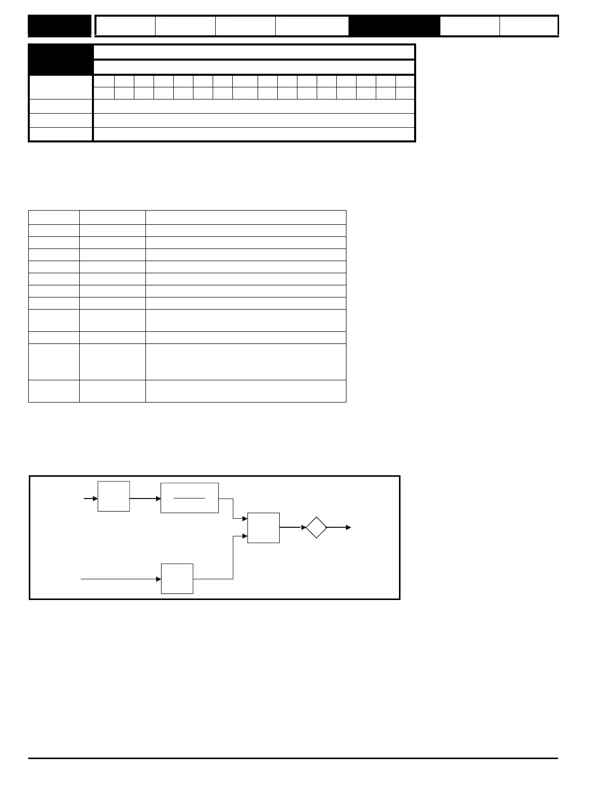
The sectional control function is intended to apply scaling and a speed offset to a 16 bit position value to generate a new 16 bit position value. The
output can be used as an input to the position controller (menu 13) or to generate an encoder simulation output via the SM-Universal encoder plus
module. This function can be selected for either variable selector, but the description below relates to variable selector 1.
The position input can be derived from any parameter, however it is intended to be used with a position value that has a range from 0 to 65535. The
input is scaled so that as Pr 12.13 is varied between -4.000 and 4.000 the proportion of the input position change added to the accumulator varies
from 0.000 to 2.000 (i.e. the change of position input value is added without scaling if Pr 12.13 is 0.000). The remainder from the scaling division is
stored and then added at the next sample to maintain an exact ratio between the position input and the position output, provided the speed input is
zero. The controller only takes the change of position from the input source parameter, and not the absolute value, so that when the controller is first
made active the output does not jump to the source position, but only moves with any changes of source position after that point in time.
The range of the output of the accumulator is 0.00 % and 100.00 %. Unlike other functions the value is not simply limited, but rolls under or over
respectively. Although the output destination can be any parameter it is intended to be used with a position value that has a range from 0 to 65535.
The speed input defines a speed offset with a resolution of 0.1 rpm. Full scale of the source parameter corresponds to 1000.0 rpm. Scaling may be
applied using Pr 12.14 to give a full scale value of 4000.0 rpm. The speed input is added to the accumulator to move the output position forwards or
backwards with respect to the position input.
12.15 Variable selector 1 control
12.35 Variable selector 2 control
Coding
Bit SP FI DE Txt VM DP ND RA NC NV PT US RW BU PS
2 111
Range 0.00 to 100.00
Default 0.00
Update rate Background
Mode value Action Result
0 Select input 1 output = input1
1 Select input 2 output = input2
2 Add output = input1 + input2
3 Subtract output = input1 - input 2
4 Multiply output = (input1 x input2) / 100.0
5 Divide output = (input1 x 100.0) / input2
6 filter output = input1 / ((control param)s + 1)
7 Linear ramp
output = input1 via a ramp with a ramp time of (control
param) seconds from 0 to 100 %
8 Modulus output = | input1 |
9 Powers
control = 0.02: output = input1
2
/ 100.0
control = 0.03: output = input1
3
/ 100.0
2
control has any other value: output = input1
10 Sectional control
control = 0.00: disabled, accumulator reset and output
zero control <> 0.00: output as defined below
4.000 + 12.13
4.000
12.14
Σ
Position
input
output
Speed
input
d/dt
Accumulator