EasyManua.ls Logo

Control Techniques Mentor MP User Manual

Control Techniques Mentor MP
214 pages
To Next Page IconTo Next Page
To Previous Page IconTo Previous Page
Page #50 background imageLoading...
Page #50 background image
Menu 3
Parameter
structure
Keypad and
display
Parameter x.00
Parameter description
format
Advanced parameter
descriptions
Serial comms
protocol
Performance
50 Mentor MP Advanced User Guide
www.controltechniques.com Issue Number: 4
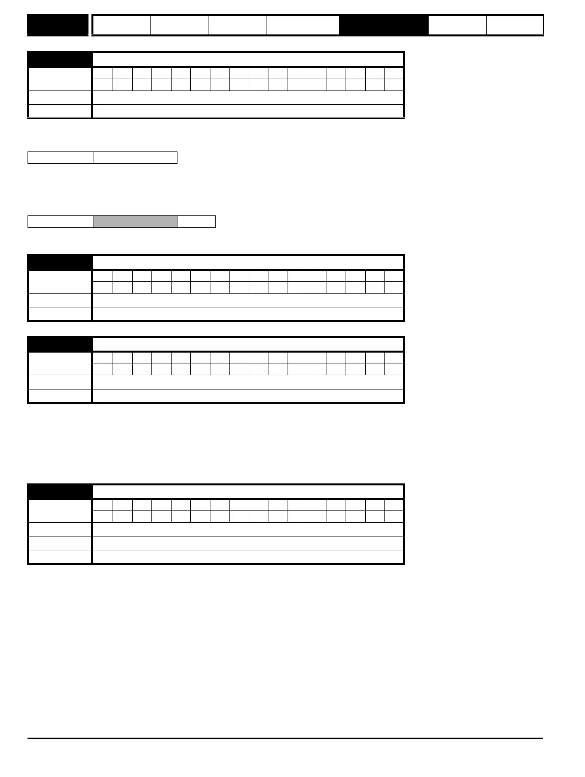
These parameters effectively give the encoder position with a resolution of 1/2
16
ths of a revolution as a 32 bit number as shown below.
Provided the encoder setup parameters are correct, the position is always converted to units of 1/2
16
ths of a revolution, but some parts of the value
may not be relevant depending on the resolution of the feedback device. For example a 1024 line digital encoder produces 4096 counts per
revolution, and so the position is represented by the bits in the shaded area only.
When the encoder rotates by more than one revolution, the revolutions in Pr 3.28 increment or decrement in the form of a sixteen bit roll-over counter.
An incremental digital encoder may have a marker channel. When this channel becomes active it may be used to reset the encoder position and set
the marker flag (Pr 3.31 = 0), or just to set the marker flag (Pr 3.31 = 1). The marker flag is set each time the marker input becomes active, but it is not
reset by the drive, and so it must be cleared by the user.
If Pr 3.35 is set to zero the marker system operates in a conventional manner and only resets the position (Pr 3.29) and not the turns (Pr 3.28) on a
marker event. If Pr 3.35 is set to one the whole position (Pr 3.28 and Pr 3.29) are reset on a marker event. The full reset mode allows the marker to
give a form of registration where the marker event defines zero position.
This parameter has a different function depending on the type of encoder selected with Pr 3.38 and Pr 3.39.
It is sometimes desirable to mask off the most significant bits of the revolution counter of encoders. This does not have to be done for the drive to
function correctly. If Pr 3.33 is zero the revolution counter (Pr 3.28) is held at zero. If Pr 3.33 has any other value it defines the maximum number of
the revolution counter before it is reset to zero. For example, if Pr 3.33 = 5, then Pr 3.28 counts up to 31 before being reset.
3.29
Drive encoder position
Coding
Bit SP FI DE Txt VM DP ND RA NC NV PT US RW BU PS
11111
Range
0 to 65,535 (1/2
16
ths of a revolution)
Update rate 4 ms write
31 16 15 0
Revolutions Position
31 16 15 4 3 0
Revolutions
Position
3.31
Drive encoder marker position reset disable
Coding
Bit SP FI DE Txt VM DP ND RA NC NV PT US RW BU PS
111
Default 0
Update rate Background read
3.32
Drive encoder marker flag
Coding
Bit SP FI DE Txt VM DP ND RA NC NV PT US RW BU PS
111
Default 0
Update rate 250 μs write
3.33
Drive encoder turns bits
Coding
Bit SP FI DE Txt VM DP ND RA NC NV PT US RW BU PS
111
Range 0 to 16
Default 16
Update rate Background read (Only has any effect when the drive is disabled)

Table of Contents

Question and Answer IconNeed help?

Do you have a question about the Control Techniques Mentor MP and is the answer not in the manual?

Control Techniques Mentor MP Specifications

General IconGeneral
Control MethodDigital
Control ModesSpeed, Torque
Communication OptionsRS485, CANopen, Ethernet
Protection ClassIP20
FeedbackEncoder
Protection FeaturesOvercurrent, Overvoltage, Undervoltage, Overtemperature, Field loss
Enclosure RatingIP20

Summary

General Information

Drive firmware version

Information about the drive's current firmware version and compatibility.

Environmental statement

Commitment to minimizing environmental impacts and EMS certification.

REACH legislation

Information on the REACH regulation regarding substances of very high concern.

Parameter Structure

Menu 0 (sub block)

Accessing Menu 0 in sub-block mode and customization options.

Pre-defined sub blocks

Details on pre-defined sub blocks and their enable/disable parameters.

Menu 0 (linear)

Description of Menu 0 when accessed in linear mode.

Advanced menus

Overview of advanced menus and keypad compatibility.

Solutions Modules

Recognition and configuration of Solutions Modules.

Menu 1: Speed reference

Analog reference

Configuration of analog inputs for speed reference.

Preset reference

Setup of preset speed references and selectors.

Keypad reference

Using the keypad for speed reference input.

Precision reference

High-resolution speed reference using precision settings.

Menu 2: Ramps

Acceleration rate selector

Selection of acceleration rates for drive control.

Deceleration rate selector

Selection of deceleration rates for drive control.

S ramp enable

Enabling and configuring S-shaped ramp profiles.

Menu 3: Speed feedback and speed control

Speed accuracy and resolution

Details on speed accuracy and resolution for different feedback types.

Analog feedback resolution

Resolution of armature voltage and tachometer feedback.

Menu 4: Torque and current control

Current measurement

Parameters related to current measurement and magnitude.

Overload detection

Configuration for overload detection and thermal protection.

Menu 5: Motor and field control

Armature control logic diagram

Logic diagram for armature control functions.

Field weakening enable

Enabling and configuring field weakening for motor control.

Menu 6: Sequencer and clock

Start/stop logic select

Selecting the logic for start and stop commands.

Enable stop key

Permanently enabling the stop key function.

Menu 7: Analog I/O

Hardware

Description of analog input and output terminals.

Update rate

Information on analog input and output sampling rates.

Menu 8: Digital I/O

I/O state

Sample rates and functions for digital I/O terminals.

I/O polarity select

Changing logic polarity for digital inputs and outputs.

Menu 9: Programmable logic, motorized pot and binary sum

Logic block functions

Description of logic block functions (AND, OR, XOR, Flip-flops).

Motorized pot function

Configuration of the motorized potentiometer function.

Menu 10: Status and trips

Drive OK

Indicates the drive is not in a trip state.

Overload alarm

Alarm triggered by high drive output current.

Menu 11: General drive setup

Parameter scaling

Scaling of parameter values for keypad display.

Serial address

Defining the unique address for the drive's serial interface.

Menu 12: Threshold detectors, variable selectors and brake control function

Threshold detectors function

Logic signals based on variable value comparison to thresholds.

Variable selectors function

Selecting or combining input parameters for output.

Brake control function

Control of an electro-mechanical brake via drive digital I/O.

Menu 13: Position control

Position control reference position

Defining the position reference from various sources.

Position control feedback position

Selecting the source for position feedback.

Menu 14: User PID controller

PID main reference source

Selecting the source for the PID controller's main reference.

PID feedback source

Selecting the source for the PID controller's feedback.

Menus 15, 16 and 17: Solutions Module slots

Solutions Module ID

Identifies the type of Solutions Module installed in a slot.

Solutions Module error status

Status of any errors detected in the Solutions Module.

Menu 18: Application menu 1

Application menu 1 power-down saved integer

Application menu 1 integer parameter saved on power-down.

Menu 19: Application menu 2

Application menu 2 power-down saved integer

Application menu 2 integer parameter saved on power-down.

Menu 20: Application menu 3

Application menu 3 read-write integer

Application menu 3 integer parameter that can be read/written.

Menu 21: Second motor parameters

Maximum reference clamp

Sets the maximum limit for the speed reference.

Minimum reference clamp

Sets the minimum limit for the speed reference.

Menu 23 Header definitions

Sub block headers

Defines the header parameters for Menu 0 sub blocks.

Pre-Defined Sub Blocks

Lists the pre-defined sub blocks and their corresponding Menu 0 parameters.

Serial Communications Protocol

6.1 ANSI communications protocol

Details the ANSIx3.28 communication protocol implementation for Mentor MP.

6.2 CT Modbus RTU specification

Describes the adaptation of the MODBUS RTU protocol for Control Techniques products.

Performance

7.1 Digital speed reference

Accuracy and resolution for digital speed references.

7.2 Analog reference

Update rates for analog reference inputs.

7.3 Analog outputs

Resolution and update rates for analog outputs.

7.4 Digital inputs and outputs

Response times for digital inputs and outputs.

7.5 Current feedback

Accuracy and resolution of current feedback.

7.6 Bandwidth

Speed and current loop bandwidth specifications.

Related product manuals