Menu 5
Parameter
structure
Keypad and
display
Parameter x.00
Parameter
description format
Advanced parameter
descriptions
Serial comms
protocol
Performance
72 Mentor MP Advanced User Guide
www.controltechniques.com Issue Number: 4
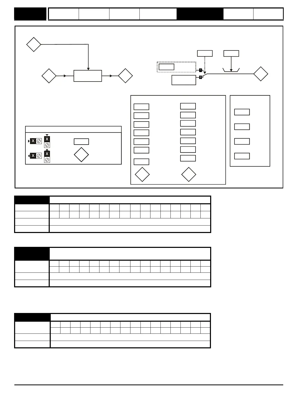
Figure 5-6 Menu 5 armature control logic diagram
0 equals fully phased forward.
The average measured DC output voltage seen across the drive A1 and A2 terminals or the average measured DC output voltage seen across the
motor. Selected by Pr 5.14.
The armature voltage feedback has a resolution of 10-bit plus sign.
Power = Armature voltage x Armature current.
5.01 Armature firing angle
Coding BitSP FI DETEVMDPNDRANCNVPTUSRWBUPS
111111
Range 0 to 175.0°
Update rate
5.02
{di02, 0.45}
Armature voltage
Coding
BitSP FI DETEVMDPNDRANCNVPTUSRWBUPS
1 1111
Range ±ARMATURE_VOLTAGE_MAX V
Update rate Background write
5.03 Output power
Coding
Bit SP FI DE TE VM DP ND RA NC NV PT US RW BU PS
112111
Range ±POWER_MAX kW
Update rate Background write
5.03
Output
power
5.02
Armature
voltage
5.13
Continuous
angle
Power
calculation
4.02
Armature
current
5.15
Motor constant
5.25
Disable adaptive
control
5.26
Continuous
autotune
5.32
Motor torque
per amp
General
5.07
Motor rated
current
5.09
Armature rated
voltage
5.12
Autotune
5.45
5.44
Bridge request
output
5.46
0.XX
0.XX
Key
Read-write (RW)
parameter
Read-only (RO)
parameter
Input
terminals
Output
terminals
5.28
Field weakening
compensation
disable