Home
CUMMINS
Engine
QST30
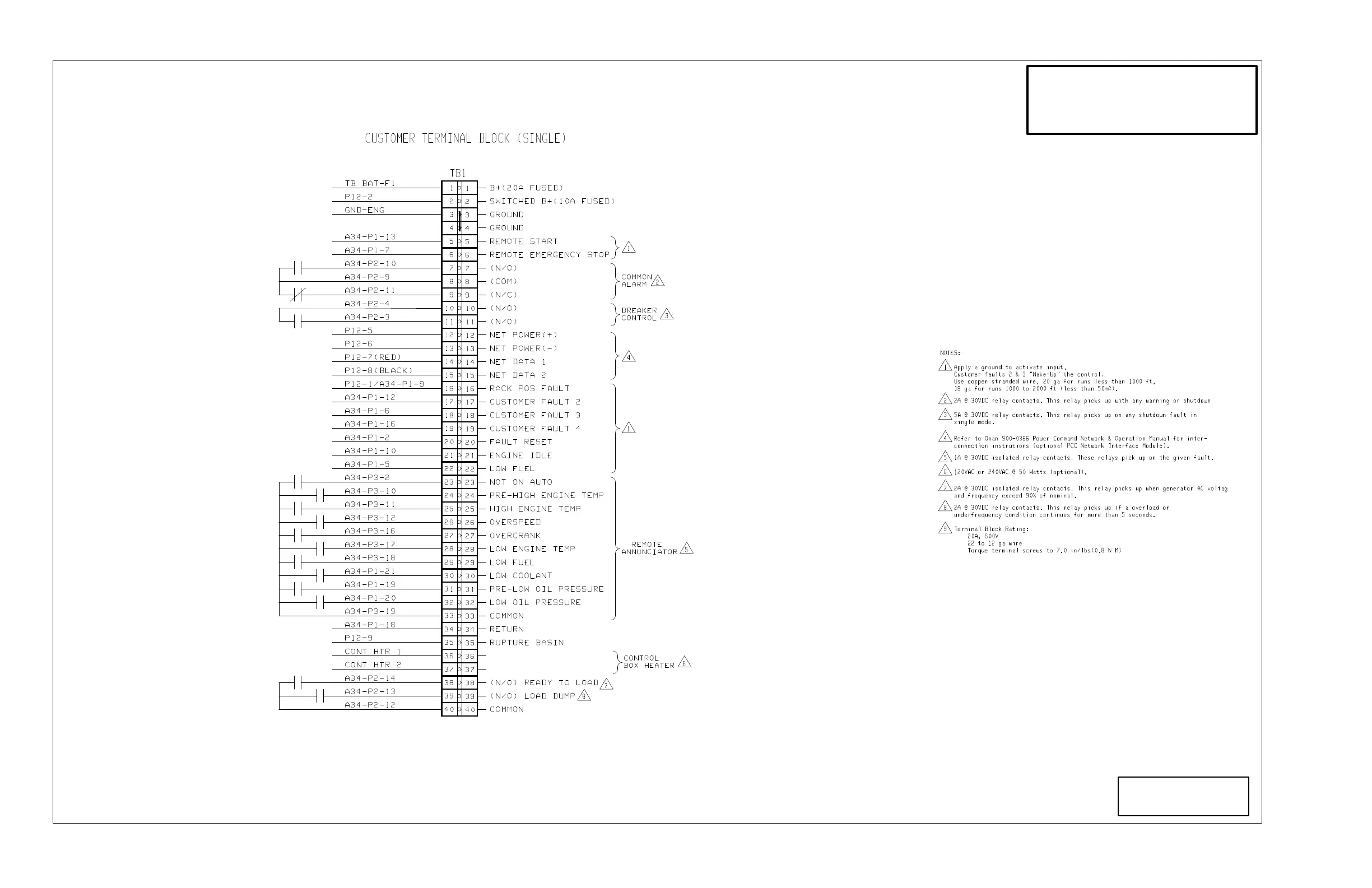
Page 161 (Customer Terminal Block)
CUMMINS QST30 - Customer Terminal Block
183 pages
Manual
Save Page as PDF
To Next Page
To Next Page
To Previous Page
To Previous Page
Loading...
A-7
Copyright
2017 Cummins Inc.
No.
sh 3 of 3
Rev
. Sys:
Modified
THIS IS A REPRESENT
A
TIVE (GENERIC)
SCHEMA
TIC/WIRING DIAGRAM. FOR
TROUBLESHOOTING, REFER TO THE
WIRING DIAGRAM P
ACKAGE THA
T W
AS
INCLUDED WITH YOUR GENSET
.
160
162
Table of Contents
Main Page
Table of Contents
3
Important Safety Instructions
7
Exhaust Gases Are Deadly
7
Fuel and Fumes Are Flammable
7
General Safety Precautions
8
Containerized Rental Units Potential Tipping Problem
8
Jack Stands at Nose of Container
9
Introduction
11
Test Equipment
11
How to Obtain Service
11
System Overview
12
Generator Set Control Function
12
Generator Set Control Functions
12
Control Operation
13
General
13
Safety Considerations
13
Pcc Power On/Standby Mode
13
Front Panel
14
Display Menu Selection Switches
15
Self Test Switch
15
Panel Lights Switch
15
Phase Selector Switch and Indicators
15
Digital Display and Menu Selection Switches
16
Menu Display and Switches
16
Main Menu
16
Engine Menu
18
OIL/COOLANT Submenu
18
BATTERY/HOURS Submenu
18
RPM/EXHAUST Submenu
18
Engine
19
Gen Menu
20
VOLTS/AMPS Submenu
20
Gen
21
Circuit Boards and Modules
23
Circuit Board Locations
23
Block Diagram
24
Digital Board
25
Switch
25
Leds
25
Connectors
25
Engine Interface Board (A31)
26
Fuses
26
DS10 GOV Duty Cycle
26
Engine Interface Board
27
Analog Board (A33)
28
Digital Display Board (A35)
29
Customer Interface Board (A34)
30
Customer Interface Board
31
Pt/Ct Board (A36)
32
Voltage Regulator Output Module
33
Governor Output Module (A38)
34
Troubleshooting
35
Status Indicators
36
Resetting the Control
36
Warning and Shutdown Codes
37
Pcc Oil Pressure Warning & Shutdown Limits
45
Troubleshooting Procedure
46
Engine Does Not Crank—Local or Remote Run
48
High Engine Temperature Warning (211) or Shutdown
60
Low Coolant Warning or Shutdown
61
Mag Pickup Shutdown
62
Overspeed Shutdown
63
DC (Battery) Warnings
64
Low Fuel −Day Warning
65
Low Fuel Warning
66
Eeprom Error Shutdown (250) or Warning
67
Rack Position Warning
68
Customer Faults
69
High Ac Voltage Shutdown
70
Low Ac Voltage Shutdown
73
Under Frequency Shutdown
75
Overcurrent Warning (320) or Shutdown
76
Short Circuit Shutdown
76
Overload Warning
76
Troubleshooting Analog Signals between Analog and Digital Boards
77
Pcc Fuses
80
Rack Position Fault/Test Procedure
81
Control Service and Calibration
83
Circuit Board Removal/Replacement
83
Control Panel Recalibration
83
Circuit Board Removal Safety Precautions
85
Wrist Strap
85
Initial Start Setup Menu
86
Initial Start Setup
87
Adjust Menu
88
VOLTAGE Submenu
88
FREQUENCY Submenu
88
START DELAY Submenu
88
Setup and Calibration Menus
90
ENTER CODE Submenu
90
Version and Displays Menus
90
Version & Displays Menus
91
DISPLAYS Submenus
92
SAVE/EXIT Submenu
92
Meters Menu
94
Governor/Regulator Menu
96
Setup Menu
98
Setup Defaults
98
SETUP Submenu
98
TORQUE ADJ %DC Submenu
98
Calibration Procedure
102
Voltage and Frequency Adjustment
102
Digital Voltage Display Calibration
102
Digital Ammeter Display Calibration
103
Digital Power Factor Display Calibration
103
Digital Coolant Temperature Display Calibration
103
Analog Meter Calibration
103
Engine Torque Adjustment
104
Accessory Box Control Components
104
Accessory Box Components
105
+TB1 Customer Inputs
106
TB1 Customer Outputs
106
Run Relays (K11, K12, K13)
107
Optional Run Relays
107
Alarm Relay (K14)
108
Optional Alarm Relay
108
RTD Relay (Optional)
109
Temperature Relay Connections
109
Thermistor Relay (Optional)
110
Engine Sensors
111
Engine Sensor Locations
112
Magnetic Speed Pickup Unit (Mpu) Installation
113
Mpu Sensor
113
Current Transformer (Ct) Installation
114
CT Installation Requirements
114
Digital Board (A32) Calibration
115
Digital Box
116
Servicing the Alternator
117
Typical Alternator
117
Alternator/Pcc Control Isolation Procedure
118
Testing the Alternator
119
Insulation Resistance Testing
119
Alternator Insulation Resistance
119
Drying the Windings
120
Exciter Stator
121
Testing the Exciter Stator
121
Winding Resistance Values
121
Exciter Rectifier Bridge (Rotating Rectifier Assembly)
122
Testing Diodes
122
Replacing Diodes
122
Surge Suppresser Testing and Replacement
122
Exciter Rotor
123
Testing Winding Resistance
123
Testing Winding Insulation Resistance
123
Testing the Exciter Rotor
123
Main Rotor (Alternator Field)
124
Insulation Resistance and PI Test
124
Testing the Main Rotor
124
Main Stator
125
Testing Main Stator Winding Resistance
125
Testing the Alternator Stator
125
Testing the Pmg
126
Bearing Inspection
127
Bearing Removal
127
P7 Bearing Removal
127
P7 Bearing Replacement
127
HC6 Bearing Removal
128
HC6 Bearing Replacement
128
HC6 Bearing Lubrication
128
Alternator Disassembly
129
Permanent Magnet (PMG) Removal
129
Permanent Magnet (PMG) Installation
129
Hc6 Alternator and Control Housing Assembly
130
P7 Alternator and Control Housing Assembly
130
Main Stator and Rotor Removal
131
Removing Control Housing
132
Hc6 Alternator Lifting Positions
133
P7 Lifting Position
134
Removing Hc6 Stator Assembly
135
Removing P7 Stator Assembly
136
Typical Alternator Assembly
138
Alternator Assembly Removal
139
Alternator Reassembly
140
Aligning Alternator with Engine
143
Angular Misalignment
143
Axial Misalignment
143
Misalignment Symptoms
143
Angular Alignment Procedure
144
Angular Alignment Measurement
144
Sample Alternator Runout Readings
145
Angular Alignment Measurement Readings
145
HC6 Axial Alignment Procedure
146
Hc6 Axial Alignment Measurement
146
P7 Axial Alignment Procedure
147
Optional Enclosure Fuel Tank System
149
Wiring Connections
149
Fuel Transfer Control Customer Outputs
149
PCC Customer Inputs
149
Fuel Transfer Pump
150
Control Panel Switches and Indicators
150
Switches
150
Indicators
150
Transfer Pump Control Front Panel
151
External/Internal Alarm Panels
152
Overfill Indicator/Horn/Silence Button
152
Fuel Gauge
152
Test Button
152
Rupture Basin Leak Detect Switch Test
153
Rupture Basin Leak Detect Switch
153
Wiring Diagrams
155
Generators
157
Related product manuals
CUMMINS QSL9
11 pages
CUMMINS QSK19
51 pages
CUMMINS QSB6.7
51 pages
CUMMINS QSK23 Series
944 pages
CUMMINS QSK19 Series
634 pages
CUMMINS QSB6.7 CM2250 EC
163 pages
CUMMINS QSB4.5 CM2350 B106
181 pages
CUMMINS QSB6.7 CM2350 B105
209 pages
CUMMINS Marine QSB6.7 CM2250
157 pages
CUMMINS 5.9
461 pages
CUMMINS M11 Series
926 pages
CUMMINS ISB Series
3 pages