EasyManua.ls Logo

Curtis Instruments 1351 User Manual

Default Icon
144 pages
To Next Page IconTo Next Page
To Previous Page IconTo Previous Page
Page #129 background imageLoading...
Page #129 background image
APPENDIX A — VCL FUNCTIONS
pg. 123
Return to TOC Curtis Model 1351 – December 2018
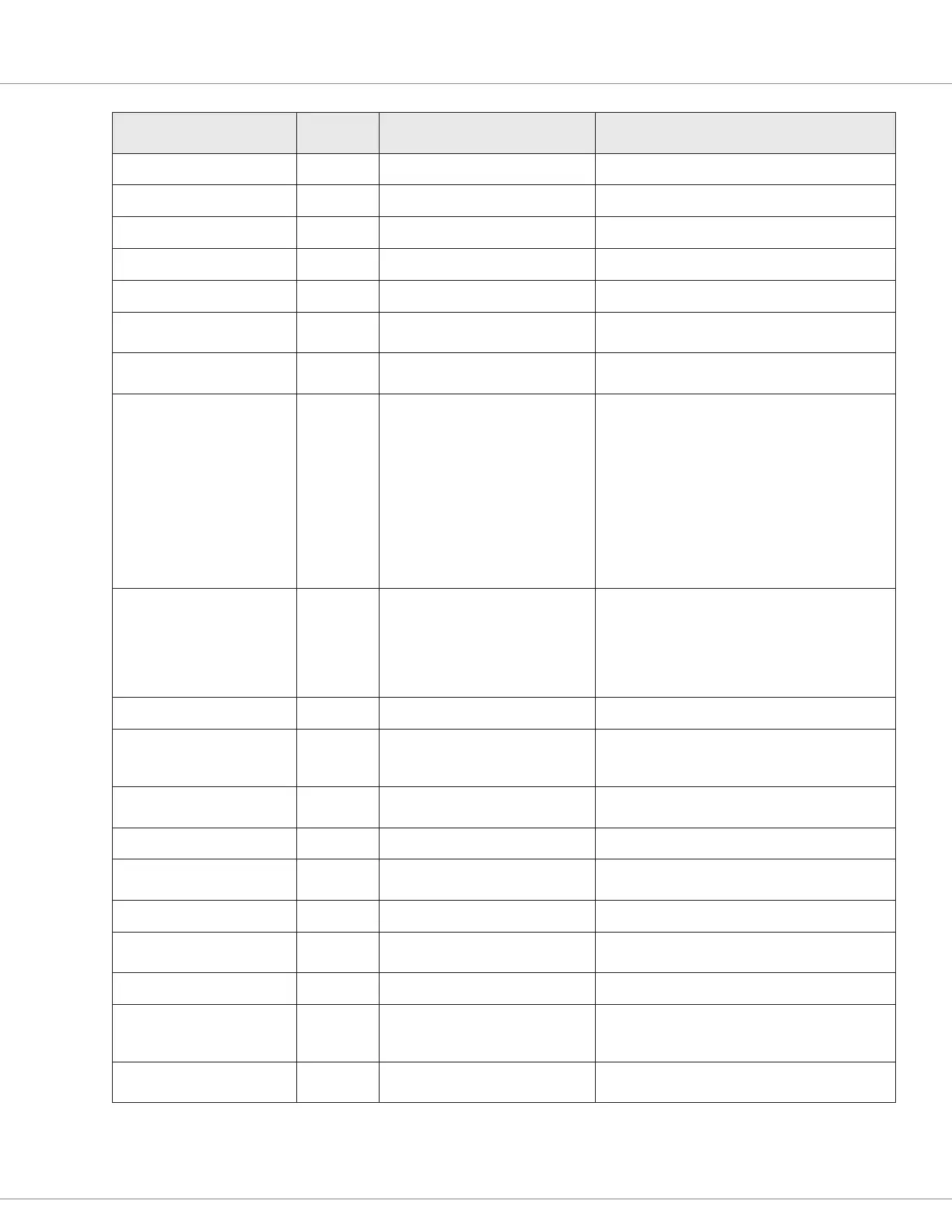
Function Name
new/unique to 1351 = ()
Arguments Short Comment Description
Get_Transmit_Status 1 (Handle) VCL_FUNCTION get_transmit_status
Clear_Transmit_Status 1 (Handle) VCL_FUNCTION clear_received_transmit_status
Get_Receive_Timeout 1 (Handle) VCL_FUNCTION get_receive_timeout
Get_Receive_ID 1 (Handle) VCL_FUNCTION Get the received arbitration ID
Clear_Receive_Timeout 1 (Handle) VCL_FUNCTION clear_receive_timeout
Assign_CAN_Mailbox 2 (port, function) Mailbox_handle: Assigned a value to identify the
mailbox that is assigned
Automate_Copy 3 Copy a Variable to another location
automatically
This function copies a variable from source to
destination
Automate_Block_Copy 4 Copy a block of Variables to
another location automatically
This function allows you to copy a sequential
block of variables from one location to another
location. The source and destination blocks
cannot overlap. The source and destination blocks
full range must be within the variable table,
otherwise a PT_RANGE error will be issued. If
you want to disable automatic copying, simply
set all parameters, except the ID, to zero (e.g.,
automate_block_copy(CPY3,0,0,0). If you do
not set the length to zero, then it is likely that a
PT_RANGE error will occur.
Automate_Limited_Block_
Copy
9 Copy a block of Variables to
another location automatically
This function allows you to copy four variables
from one location to another location. The source
and destination address for each variable to
transfer must be specied. A source/destination
pair will be ignored (i.e., not transferred) if either
the source or the destination value is set to zero.
Setup_Delay 2 Setup a Time Delay This function installs a new time delay
Setup_Delay_PreScale 2 Setup a Delay Timer’s pre-scale This routine setups up a pre-scale for time delay
block. The default pre-scale is 1 (i.e., the timer
counts down at a 1ms rate).
Automate_Filter 5 Filter a value This function initiates ltering on the selected
variable
Setup_Limit 3 Setup a Limit Function This function installs new value for a limit block
Automate_Limit 3 VCL - Automate a Limit Function This function sets one or more of the values in a
limit block to be automatically updated
Set_Limit 2 Set the Limit Value This function installs new value for a limit
Get_Limit 2 Get the Limited Value This function returns the input ‘clamped’ by the
limit
Setup_Map 16 Setup a map This function species a map.
Automate_Map 2 Set the mapping up to be done
automatically
This function allows you to set up a map that runs
automatically. The ‘source’ is the variable that will
be mapped.
Get_Map_Output 2 Interpolate within a 2D table of N
entries
This function maps the input variable to a new
value using the specied map.

Table of Contents

Questions and Answers:

Curtis Instruments 1351 Specifications

General IconGeneral
CategoryI/O Systems
Model1351
Operating Temperature Range-40°C to +85°C
Protection FeaturesOvervoltage, Short Circuit
Communication InterfaceCAN 2.0B

Summary

1 — OVERVIEW

How to Use This Manual

Explains how to use the manual's content and structure.

Getting the Most Out of Your Curtis Controller

Tips for optimal use and contact for technical support.

2 — INSTALLATION SPECIFICATIONS AND WIRING

Mounting and Safety Precautions

Guidelines for physical mounting and general safety warnings.

Wiring and Connections

Details on AMPSEAL connector, battery, low-power wiring, and voltages.

Input/Output Configuration

Overview of various input and output types and their configurations.

Communication Ports and Power

Details on CAN ports, power supply outputs, and keyswitch connections.

3 — PROGRAMMABLE PARAMETERS

Programming Menus and Format

Overview of parameter menus, chart format, and terminology.

System Controller Parameters

Parameters for power, BDI, external supplies, and temperature.

Input Parameters

Configuration for switches, virtual switches, analog, pot, RTD, high-speed, encoder inputs.

Output Parameters

Configuration for PWM drivers, half-bridge, digital drivers, safety, and analog outputs.

CAN Parameters

Settings for CAN ports and communication protocols.

4 — MONITOR VARIABLES

System Controller Monitor Variables

Read-only variables for system controller status and measurements.

Input Monitor Variables

Read-only variables for various input types like switches, analog, and encoders.

Output Monitor Variables

Read-only variables for PWM drivers, half-bridge drivers, and digital outputs.

Accelerometer Monitor Variables

Read-only variables for the 3-axis accelerometer data.

5 — VEHICLE CONTROL LANGUAGE (VCL)

VCL Overview and Basics

Introduction to VCL, its capabilities, and fundamental programming rules.

Variables and Constants

Explanation of VCL variable types, memory storage, and constants.

VCL, Watchdog Timer and Faults

Setting up watchdog timers and defining fault actions within VCL code.

CAN Functions (VCL Setup)

VCL functions for CAN setup, message handling, and NMT control.

SDO Management

VCL functions for managing Service Data Objects (SDOs) read/write operations.

CAN Mailbox Operations

Functions for allocating and configuring CAN mailboxes for data transmission/reception.

SRDO Functions

VCL functions for Safety Related Data Objects transmission and reception.

6 — INITIAL SETUP & COMMISSIONING

Initial Setup and Preparation

Steps for initial setup, safety, and preparation before commissioning.

Parameter Settings Method Overview

Recommended sequence for setting hardware and software parameters.

Output Parameter Configuration

Procedure for configuring PWM, half-bridge, digital, and analog outputs.

Fault Clearing Procedure

Steps to check, clear, and resolve controller faults and history.

7 — DIAGNOSTIC AND TROUBLESHOOTING

The Diagnostics Process

Methods for obtaining diagnostics information via LEDs, software, or CAN messages.

Error Flash Code Interpretation

Explanation of LED flash patterns and their meanings for fault codes.

8 — MAINTENANCE

Cleaning Procedures

Recommended procedure for cleaning the controller exterior.

Fault History Management

Accessing, checking, and clearing the controller's fault history file.

APPENDIX A — VCL FUNCTIONS

General VCL Functions

Core VCL functions for various operations like interpolation, timing, and scaling.

CANopen Functions

VCL functions for CANopen mailbox setup and configuration.

SRDO Functions

VCL functions for Safety Related Data Objects transmission and reception.

APPENDIX B — VEHICLE SYSTEM DESIGN CONSIDERATIONS-&-RECYCLING

Electromagnetic Compatibility (EMC)

Guidelines for EMC performance, emissions, RF immunity, and noise reduction.

Decommissioning and Recycling the Controller

Procedures for controller removal from OEM vehicle and disposal.

APPENDIX C — PROGRAMMING DEVICES FOR THE 1351

Curtis Software Suite™

PC-based software for controller setup, parameter adjustment, and diagnostics.

Curtis 1313 Handheld Programmer

Standalone programmer and diagnostic tool for the system controller.

APPENDIX D — EN 13849 COMPLIANCE

Safety-Related Performance Analysis

Summary of safety performance levels (PL, MTTFd, DC) for controller circuits.

APPENDIX E — 1351 MODELS AND SPECIFICATIONS

Table E Model Chart and Specifications

Technical specifications, model comparison, and environmental ratings.