4 — MONITOR VARIABLES
pg. 71
Return to TOC Curtis Model 1351 – December 2018
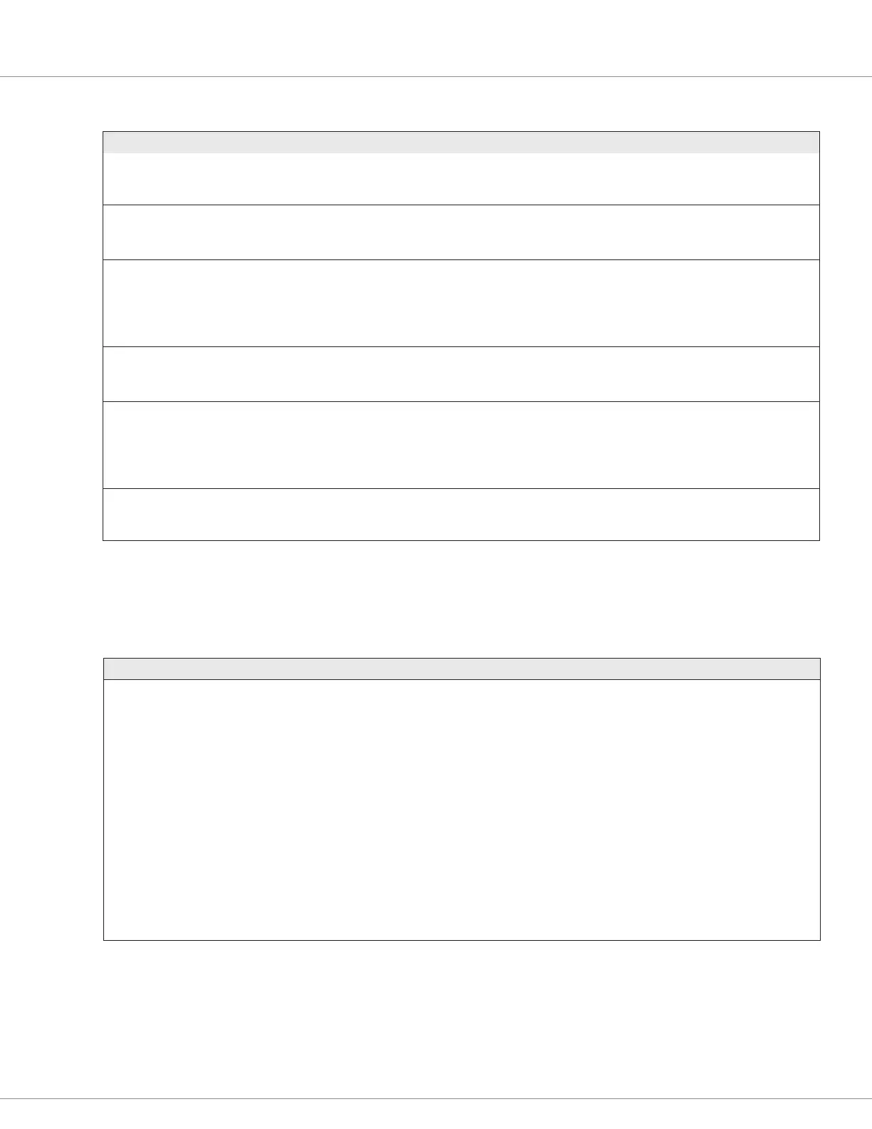
MONITOR VARIABLES: SYSTEM CONTROLLER
VARIABLE DISPLAY RANGE DESCRIPTION
Keyswitch Voltage
Keyswitch_Voltage
0x331C 0x00
0.0 – 140.0 V
0 – 14000
Voltage at the keyswitch (KSI, pin 7).
This will be at/near the battery voltage during operation.
Ext 5V
Ext_5V
0x3325 0x00
0.0 – 10.0 V
0 – 1000
The measured output voltage at the 5V supply (pin 10)
This variable is also available in the parameter External Supplies menu, see:
Configuration\System Controller\External Supplies\Ext 5V
Ext 5V Current
Ext_5V_Current
0x3327 0x00
0 – 1000 mA
0 – 1000
The measured output current at the 5V supply (pin 10)
Note, the combined load current between the +5V and +12V outputs cannot
exceed 300 mA
This variable is also available in the parameter External Supplies menu, see:
Configuration\System Controller\External Supplies\Ext 5V Current
Ext 12V
Ext_12V
0x3326 0x00
0.0 – 20.0 V
0 – 2000
The measured output voltage at the 12V supply (pin 9)
This variable is also available in the parameter External Supplies menu, see:
Configuration\System Controller\External Supplies\Ext 12V
Ext 12V Current
Ext_12V_Current
0x3328 0x00
0 – 1000 mA
0 – 1000
The measured output current at the 12V supply (pin 9)
Note, the combined load current between the +5V and +12V outputs cannot
exceed 300 mA
This variable is also available in the parameter External Supplies menu, see:
Configuration\System Controller\External Supplies\Ext 12V Current
Module Temperature
Module_Temperature
0x3329 0x00
−50.0 – 100.0°C
−500 – 1000
The internal temperature of the 1351 System Controller.
If excessive or unexpected high temperature, reconsider mounting method
and location.
MONITOR VARIABLES: INPUTS → Switch Input/Virtual Switches
VARIABLE DISPLAY RANGE DESCRIPTION
Virtual Switch X
Virtual_Switch_X
Monitor Variable CAN Index
Virtual_Switch_X
1 = 0x3380 0x00
2 = 0x3381 0x00
3 = 0x3382 0x00
4 = 0x3383 0x00
5 = 0x3384 0x00
6 = 0x3385 0x00
7 = 0x3386 0x00
8 = 0x3387 0x00
9 = 0x3388 0x00
10 = 0x3389 0x00
11 = 0x338A 0x00
0 – 1
0 – 1
0 = Off
1 = On
The Virtual Switch X state is based upon the Analog 1 Input voltage (pin 1),
the high and low thresholds set for the analog input and the VSW X Active
Level parameter settings.
Note: Replace X with 1 − 11 for the specic VSW.
See Programmer: Configuration\Inputs\Virtual Switches\VSW X\Active Level
Configuration\Inputs\Analog Inputs\Analog X\Value