2 — INSTALLATION SPECIFICATIONS AND WIRING
pg. 3
Return to TOC Curtis Model 1351 – December 2018
2 — INSTALLATION SPECIFICATIONS AND WIRING
PHYSICALLY MOUNTING THE 1351 SYSTEM CONTROLLER
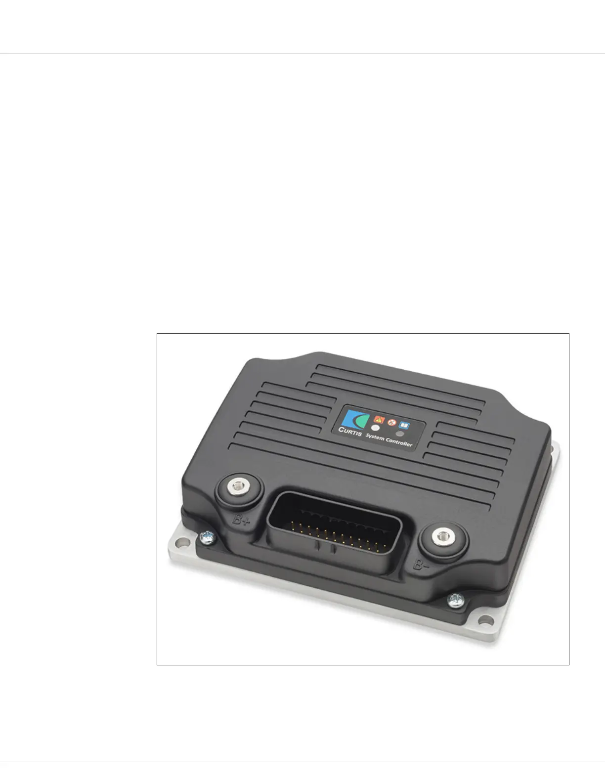
Figure 1 is the 1351 System Controller. Its outline and mounting-hole dimensions are in Figure 2.
Mount the controller to a at surface devoid of protrusions, ridges, or a curvature that can cause damage
or distortion to its heatsink (base plate). To simplify the use of the 3-axis accelerometer, mount the
1351 in a level/orthogonal orientation. Secure the controller using evenly torqued bolts to the vehicle’s
mounting surface. When mounted to a metal surface, additional heat sinking or fan cooling is not
necessary to meet the 1351’s peak and continuous current ratings.
When installed with the matching vehicle-harness connector, the 1351 system controller meets the IP65
requirements for environmental protection against dust and water. Nevertheless, in order to prevent
external corrosion and leakage paths from developing, select a mounting location that will keep the
controller as clean and dry as possible.
Figure 1
e 1351 System
Controller