2 — INSTALLATION SPECIFICATIONS AND WIRING
Curtis Model 1351 – December 2018
Return to TOC
pg. 24
Encoder Inputs
e 1351 System Controller accepts two position encoder inputs labeled as Encoder 1 and Encoder 2.
ree types of encoders can be connected:
• Quadrature Encoders with Open Collector outputs
• Sine/Cosine Position sensors
• Sawtooth Position transducer
Each type of encoder requires unique wiring and setup parameters, yet the result is the same: position
and speed measurements. Aer selecting the encoder Type, its corresponding parameter set will
become available, otherwise it is hidden. Notice that Encoder 1 shares its inputs with the High Speed
Digital Inputs (see above), thus it cannot be used as both the encoder and the high-speed inputs
simultaneously. For each type of encoder, the input signals are mathematically converted to position
and speed. In all cases, the connections are referenced to the controller’s I/O ground (pin 8).
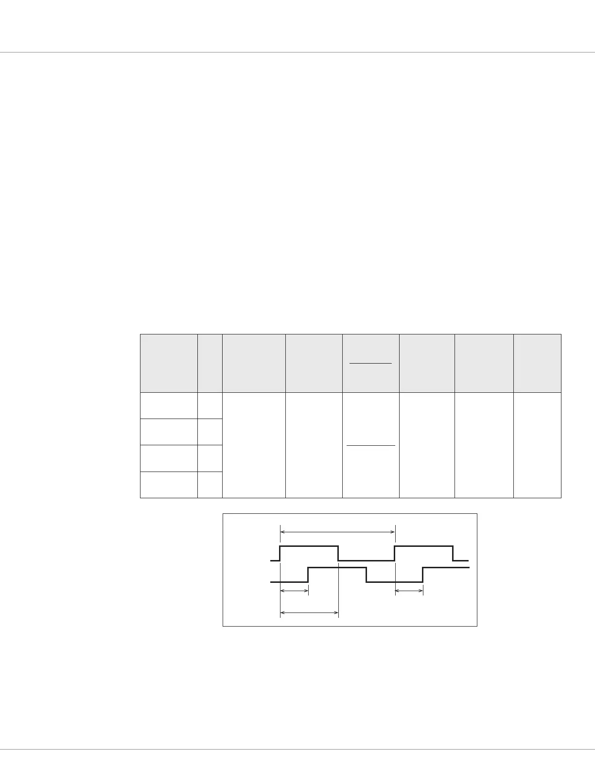
Quadrature Encoders
Table 13 Quadrature Encoder Inputs
Signal Pin
Input Voltage
Range
Logic
Threshold
Pull-Up
Resistance
Input
Impedance
Maximum
Frequency
A-B Phase
Range
Phase Duty
Cycle
ENC 1A
(Analog 4)
15
0 – 5 V
Rising edge=
2.9 V max
Falling edge=
2.0 V min
2 kΩ to 5 V
> 115 kΩ
15 kHz 90° ± 30°
50 % ±
10 %
ENC 1B
(Analog 3)
14
ENC 2A
(Analog 2)
2
ENC 2B
(Analog 1)
1
Channel A
Channel B
360° electrical (1 cycle)
>10 μs90° ±30°
180° ±18°
These quadrature encoder signal tolerances must be maintained throughout the application’s
operating conditions, including voltage and temperature, as well as speed and torque ranges when
applied to a motor. A parameter setting is available for channel A and B direction—A before B or B
before A.