2 — INSTALLATION SPECIFICATIONS AND WIRING
pg. 21
Return to TOC Curtis Model 1351 – December 2018
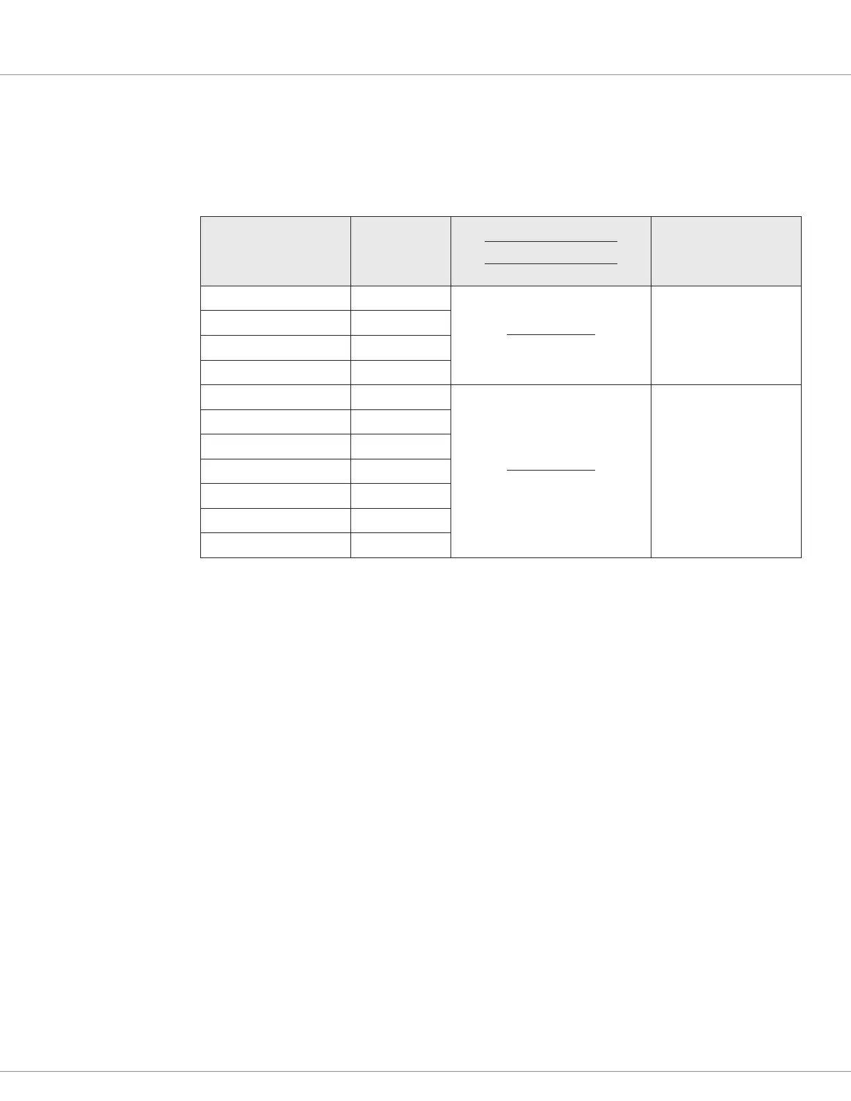
Analog (voltage) Inputs
e system controller supports a variety of analog inputs. Analog inputs measure voltage applied to
the input pin. e voltage range depends on the input used, as shown in Table 9.
Table 9 Analog (voltage) Inputs Electrical Specications
Signal Name Pin
Measurement Range
High/Low Threshold
Filter Time Constant
Input Impedance
Analog 1 1
0 – 5 V
0 – 3.000 sec
> 650 kΩ
Analog 2 2
Analog 3 14
Analog 4 15
Analog 5 16
0 – 20 V
0 – 3.000 sec
> 200 kΩ
Analog 6 17
Analog 7 18
Analog 8 19
Analog 9 20
Analog 10 21
Analog 11 22