2 — INSTALLATION SPECIFICATIONS AND WIRING
Curtis Model 1351 – December 2018
Return to TOC
pg. 18
Digital (driver) Outputs
e three digital outputs are low-side drivers with a 3-ampere current (sink) limit. As low-side drivers,
they can only be turned ON or OFF. e control modes for PWM, constant current or voltage are not
available. For inductive loads, these drivers have a y-back diode to Coil Return. Resistive loads must
not exceed the 3-amp current-sink rating. e VCL function Digital_Out_X_Command (where X is 1,
2 or 3) or Put_Driver() is used to control these drivers (where a non-zero value = ON).
Digital Output 1 can also be used as either the Encoder 2B or analog1 inputs, based upon parameter
settings. e Digital Outputs 2 and 3 parameters can be disabled for use as digital switch inputs
(Switches 11 and 12 respectfully).
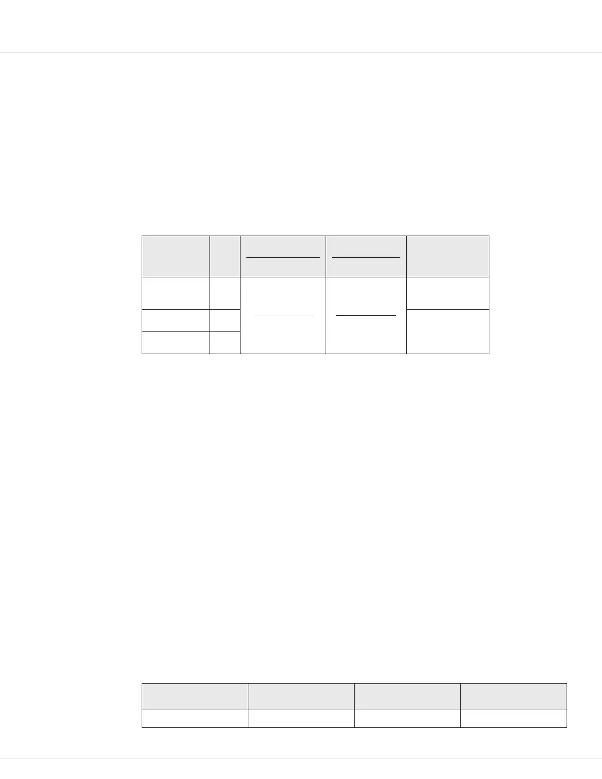
Table 6 Digital Outputs (drivers) Electrical Specifications
Signal Name Pin
Output Type
Activity Level
Output Current
Short-Circuit
Input Impedance
(Off State)
Digital Out 1 1
Low-side Driver
On/Off
3 Amps
(100% On)
< 30 Amps
for < 100μS
> 350kΩ
Digital Out 2 25
> 650kΩ
Digital Out 3 34
Safety Output
e Safety Output provides the power to all connected loads. e safety output must be enabled for
the connected drivers to operate. e Safety Output is normally used as the Coil Return connection
for low-side driver loads, but it can also be used as a high-side driver for a safety/system contactor.
Once enabled, the safety output can supply up to 23 amps of B+ voltage at the pins (in common) 11
and 12 (see the Safety Output Command parameter).
e system designer shall ensure the driver loads at pins 11 and 12 are under the combined 23-ampere
current rating. e safety output will shut down if excessive over-current or a short is detected.
Analog Output
e system controller has one analog output. is adjustable 0-10V Op Amp output is intended
to drive high-impedance loads, such as a battery discharge indicator or hour meter. is output is
generated from a ltered PWM signal and has about 1% ripple. e 2% settling time is <25 ms for
a 0–5 V step and <30 ms for a 0–10 V step. is output line is protected against shorts to B+ or B−.
e analog output is parameter settable, sharing the output with the Analog 11 input (pin 22).
Set the output voltage by setting the VCL variable Analog_Out_Command from 0–1000 (0.00 to
10.00V).
Table 7 Analog Output Specications
Signal Name Pin Output Voltage Output Current
Analog Out 22 0 to 10 V 10 mA