6 — INITIAL SETUP & COMMISSIONING
Curtis Model 1351 – December 2018
Return to TOC
pg. 112
Status) is included in each of the analog input sub-menus. It is recommended each input be veried
as part of the initial setup.
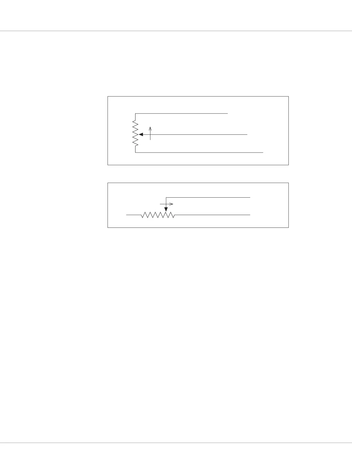
Pot Inputs require setting the Type parameter. Do this rst, and then set the resistance and tolerance
parameters. Adjust these parameters based upon the in-menu Resistance and Wiper Position monitor
variables values. Figures 5 and 6 illustrate the wiring for 3-Wire and 2-Wire potentiometers.
RTD Inputs require their type be enabled and their input-resistance versus output-value mapped.
Once the system is operational, check the RTD’s corresponding monitor variables Resistance and
Value, making adjustments to the map values to achieve the correct response.
e two High Speed Digital Inputs parameters have a Type and Direction setting. Verify the RPM
output variable is correct once the system is operational. Oen, hand spinning of an encoder’s device
(e.g., motor) can be used to nalize the parameter settings.
Refer to these pages for the Input sub-menus.
Switches: p. 38 – 41
Virtual Switches: p. 42 – 43
Analog Inputs: p. 44 – 45
Pot Inputs: p. 46
RTD Inputs: p. 47 – 48
High Speed Digital Inputs: p. 49
Encoder Inputs: p. 50 – 51
Figure 5
Wiring for 3-Wire
Potentiometer
1kΩ–10k Ω
FASTER
I/O Ground (Pin 8)
Pot High output (Pin 21)
Pot Wiper input (Pin 20)
Figure 6
Wiring for 2-Wire
Potentiometer
I/O Ground (Pin 8)
Pot Wiper input (Pin 20)
5kΩ–0
FASTER