4 — MONITOR VARIABLES
pg. 77
Return to TOC Curtis Model 1351 – December 2018
ACCELEROMETER
3-axis Accelerometer (X Y Z axis)
e 1351 comes standard with a 3-axis accelerometer. e 3-axis accelerometer can be used in
many situations, such as recording abuse (shock), to limit vehicle speed, li or reach based upon the
grade (tilt), monitor vehicle acceleration/time, or vehicle sway (roll). Implement the accelerometer
variables using VCL.
X axis
Y axis
Z axis
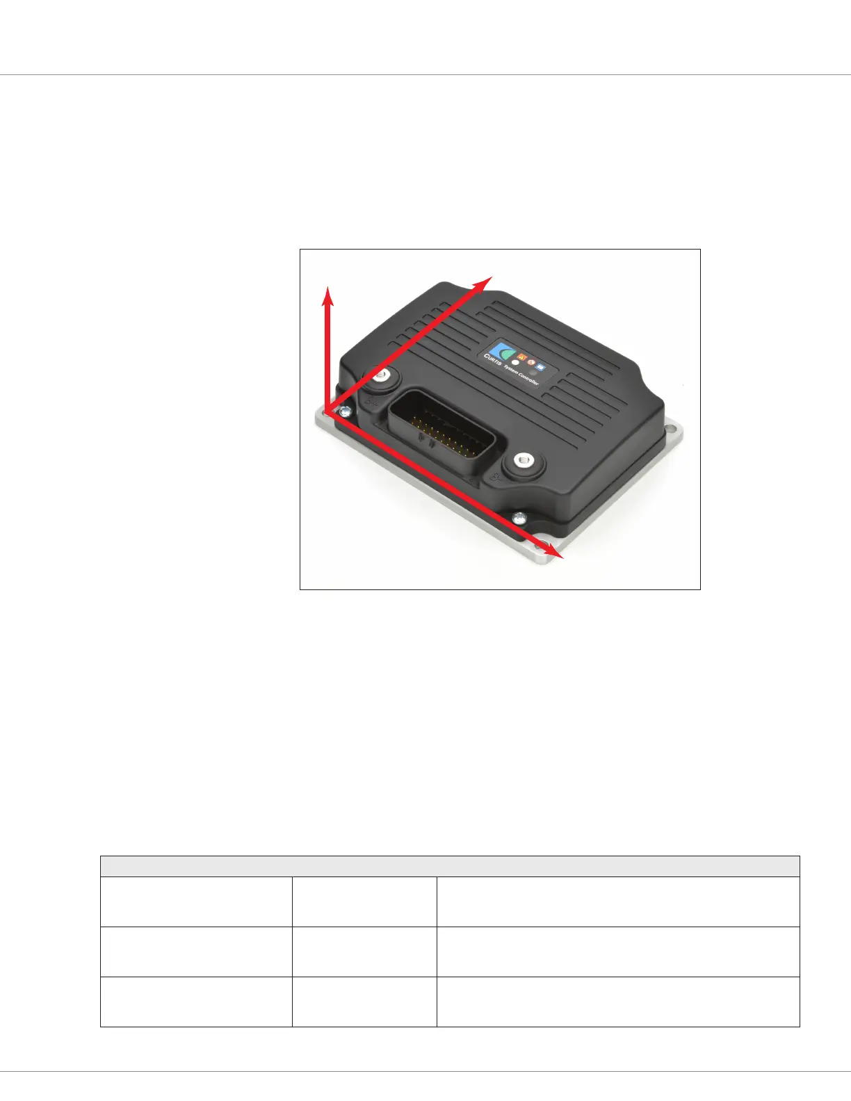
3-axis Accelerometer Orientation
X-axis e accelerometer’s x-axis is from le-to-right across the 1351. If the 1351 is placed
on its le side (B+ terminal down, B− terminal up), the accelerator’s x-axis (monitor
variable X) will read positive 1 g and approximately 0 in the other two.
Y-axis e accelerometer’s y-axis is from front-to-back on the 1351. If the 1351 is placed on
its rear side (35-pin connector down), the accelerator’s y-axis (monitor variable Y) will
read positive 1 g and approximately 0 in the other two.
Z-axis e accelerometer’s z-axis is from bottom to top on the 1351. If the 1351 is placed at
on its cold plate (connections up), the accelerator’s z-axis (monitor variable Z) will read
positive 1 g and approximately 0 in the other two.
MONITOR VARIABLES: ACCELEROMETER
VARIABLE DISPLAY RANGE DESCRIPTION
X
Sensor_X
0x3430 0x00
−20.000 – 20.000
−20000 – 20000
The X axis output signal of the 3-axis accelerometer.
Y
Sensor_Y
0x3431 0x00
−20.000 – 20.000
−20000 – 20000
The Y axis output signal of the 3-axis accelerometer.
Z
Sensor_Z
0x3432 0x00
−20.000 – 20.000
−20000 – 20000
The Z axis output signal of the 3-axis accelerometer.