2 — INSTALLATION SPECIFICATIONS AND WIRING
pg. 29
Return to TOC Curtis Model 1351 – December 2018
Keyswitch and Coil Return/Safety Output
Connect the KSI (keyswitch, pin 7) to B+ via a key switch and fuse as shown in Figure 4. e KSI
input feeds the controller’s internal power supplies before the main contactor closes. e lead-acid
Battery Discharge Indicator (BDI) uses the keyswitch voltage.
e Coil Return/Safety Output (pins 11 and 12) are derived from B+. If the 1351 will drive a contactor
that supplies power to the B+ stud, its coil must be wired to KSI (pin 7) and have its own yback
diode, because the Safety Output/Coil Return is only active if there is power on the B+ stud. Two Coil
Return pins are used to increase the available sourcing current to the 10 low-side PWM drivers. Each
of the coil return pins are limited to ~12 amperes*. Note that the peak sum of all currents possible
though all loads connected to the Coil Return shall not exceed the two KSI Coil Return’s maximum
current rating. Table 4 lists the drivers’ peak currents. e Safety Output (feature) is not PWM-able.
It is either ON or OFF.
As illustrated in the wiring diagram, Figure 4, connect the Coil Return circuits directly to one side
of the contactors’ coil terminals and the other terminal to the driver pin. e controller includes an
internal y-back diode between each Driver and Coil Return to suppress the coils’ inductive voltage
spike. Coils with their own inductive-spike suppression are allowed (but care must be made to use
the proper connections to Coil Return and the Driver output), yet resistive-based coil suppression is
discouraged because of leakage currents within the 1351 between the drivers and coil return.
Proper connections to Coil Return and B+/B− studs ensure reverse polarity protection (vehicle wiring
correct, battery terminals reversed). Reference the wiring diagram, Figure 4, for the typical KSI and
Coil Return/Safety Output connections.
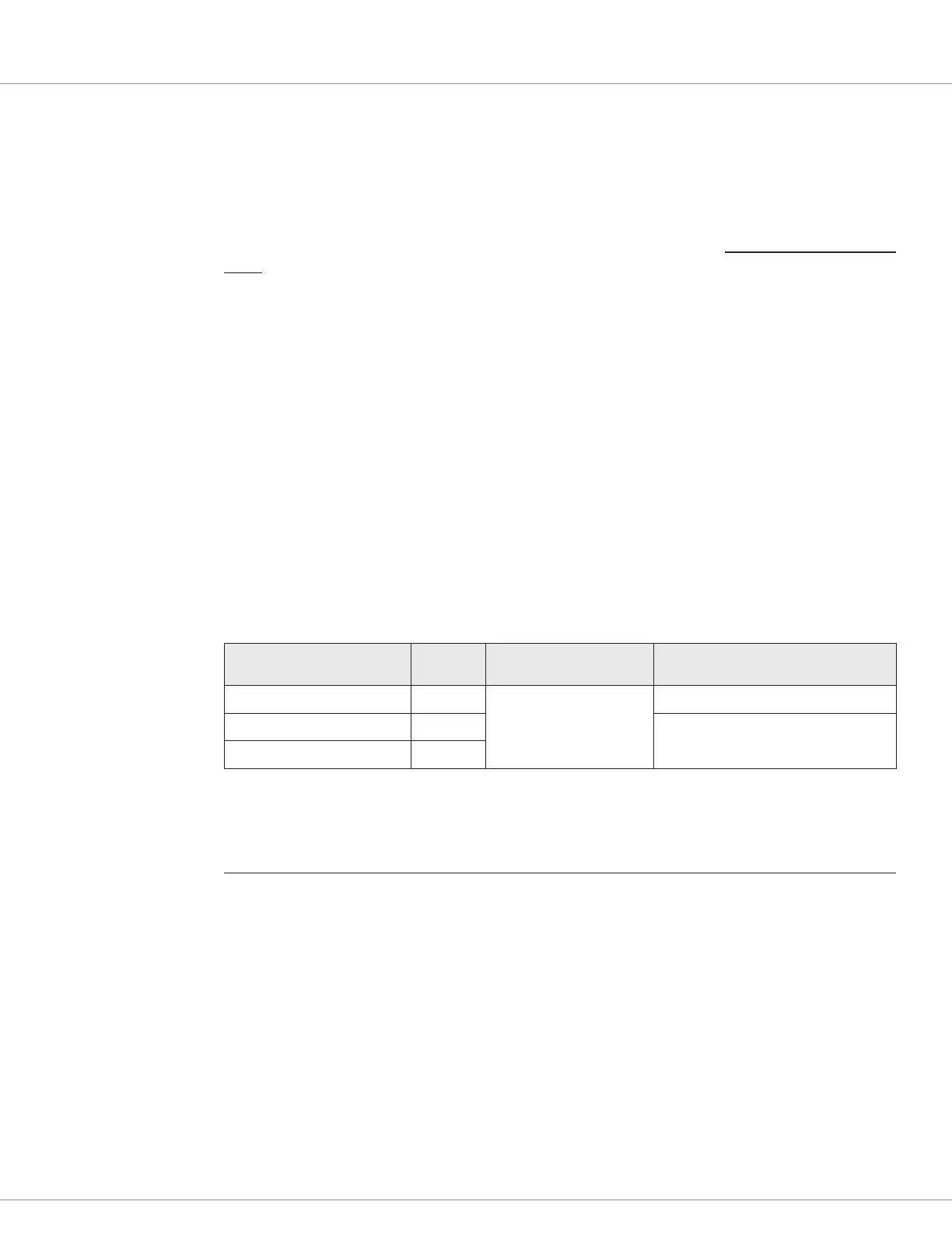
Table 18 KSI & Coil Return/Safety Output
Signal Name Pin Operating Voltage Current**
KSI (keyswitch) 7
Between the under and
over voltage cutback limits
9 A (input/sink)
Coil Return / Safety Output 11
23 amps total or ~ 12 amps per pin
Coil Return / Safety Output 12
** Gold plated terminal basis.
* See the mating contact specification (Table 1) to achieve this amp rating.