2 — INSTALLATION SPECIFICATIONS AND WIRING
pg. 23
Return to TOC Curtis Model 1351 – December 2018
Conguring an RTD sensor is based upon its changing resistance over a set of four X/Y mapping
parameters (points). Resistive input values below the map’s lower point are limited to the lower
output, while values above the maps’ upper setting are clamped to the upper output. e resistive-
values parameter points must be in an ascending/increasing order. RTD Inputs between the map’s
four resistive points are interpolated.
To use the analog input as a RTD, it must be enabled by the RTD Enable parameter (Pull Up). Note
that the Analog channel’s threshold settings will still be active for the analog input reading variables
when the RTD is enabled (see Analog Inputs parameters). is means that the Virtual Switches 5-8
can be utilized to expand the system control logic when using RTD Inputs (such as using them to
indicate a fault threshold).
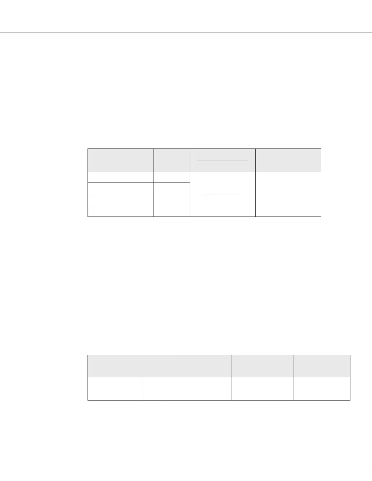
Table 11 RTD Inputs Electrical Specications
Signal Name Pin
Resistive Range
Pull-up Voltage
Input Impedance
RTD 1 16
0 – 10,000 Ω
~ 4.4V
> 178 kΩ
RTD 2 17
RTD 3 18
RTD 4 19
High Speed Digital Inputs
ere are two high-speed inputs on the 1351—High Speed Input 1 and High Speed Input 2. ese
inputs are intended to measure the frequency of incoming 5 volt pulses, the pulse width, or used as
counters/accumulators. ese two inputs can also be used for encoder inputs (see below), but cannot
be used as both high-speed inputs and encoders simultaneously.
e function of each pulse input must be set before it can be used by means of its Type parameter.
For high-speed signal processing, select when the pulse width and counter functions need to react.
e parameter also sets whether the function will look at the rising edge or falling edge. If rising
edge is selected, the pulse width and period will be measured from the rising of the signal to falling
edge and the counter will increment on each rising edge. e frequency always measures from rising
to rising edge.
Table 12 High Speed Digital Inputs
Signal Name Pin Options Input Impedance
Edge Thresholds
Rising/Falling Edge
HS Input 1 15 Frequency (Hz)
Pulse Width (%)
Counter
> 228 kΩ
~2.6V Rising
~1.3V Falling
HS Input 2 14