4 — MONITOR VARIABLES
Curtis Model 1351 – December 2018
Return to TOC
pg. 70
4 — MONITOR VARIABLES
Monitor variables are read only items intended to assist with setting-up the 1351 system controller
parameters. Use the monitor variables for 1351 faults and system diagnostic. As noted in Chapter 3,
monitor variables shown in the Programmer App’s parameter menus are the same as those in the
Monitor menu. e menu structure generally follows the parameter menu layout in terms of System,
Inputs and Outputs. e 3-axis accelerometer readout is located in the Monitor menu.
...
....
_
+
...
.....
Monitor
+
...
.....
+
...
+
...
.....
System Controller
Inputs
Outputs
Accelerometer
............. p.71
............. p.71
............. p.75
............. p.77
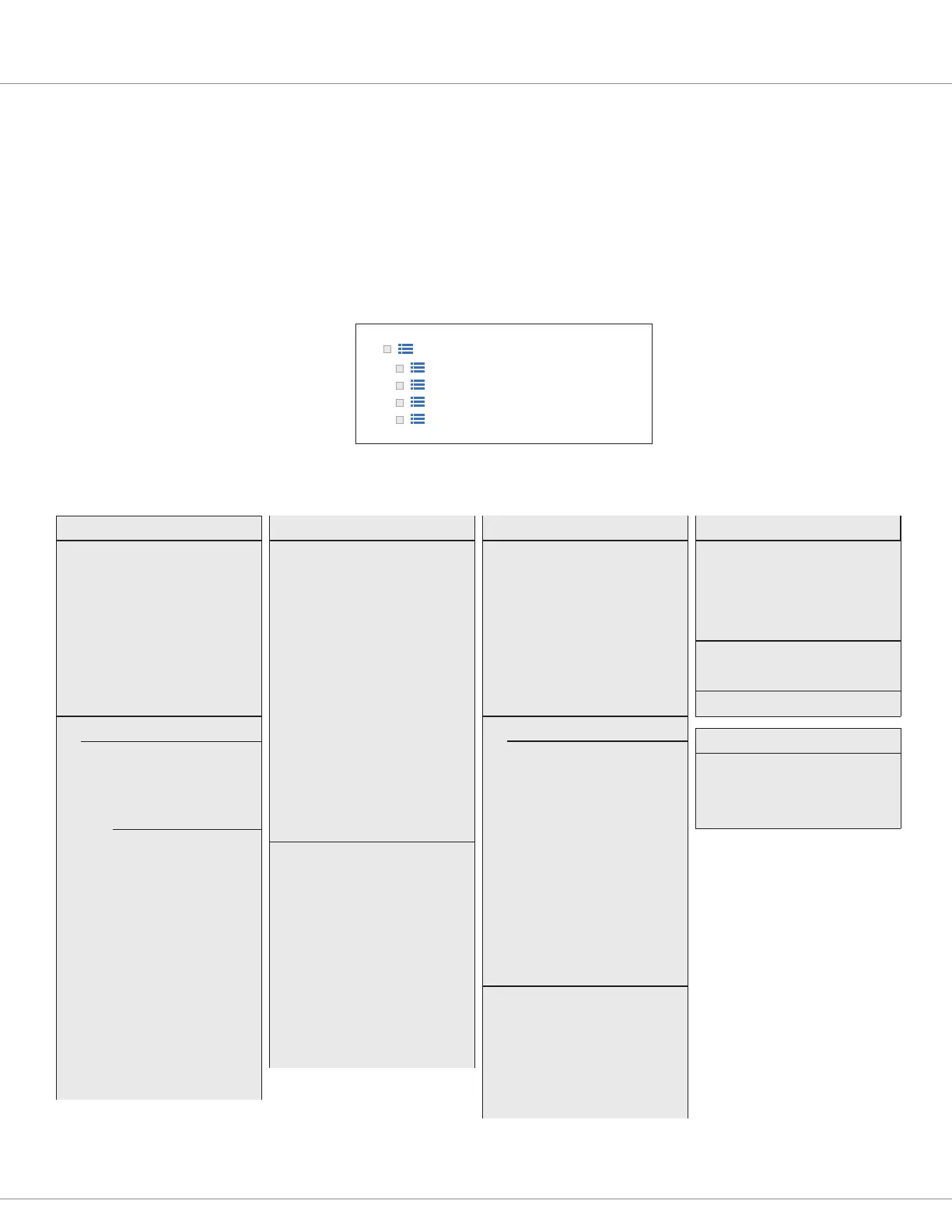
Table 20 Monitor Variables Menus
As displayed using the Curtis Soware Suite
TM
or the 1313 HHP
SYSTEM CONTROLLER....... p. 71
—Keyswitch Voltage
—Ext 5V
—Ext 5V Current
—Ext 12V
—Ext 12V Current
—Module Temperature
INPUTS............................... p. 71
SWITCH INPUT............... p. 71
—Virtual Switch 1
—Virtual Switch 2
. . . . .
—Virtual Switch 11
—Switch 1............ p. 72
—Switch 2
. . . . .
—Switch 14
ANALOG INPUT.............. p. 72
—Analog 1
—Analog 2
. . . . .
—Analog 11
POT INPUT..................... p. 73
—Wiper Position
—Resistance
RTD INPUT.......................... p. 73
—RTD1
—Resistance
—Value
—RTD2
—Resistance
—Value
—RTD3
—Resistance
—Value
—RTD4
—Resistance
—Value
HIGH SPEED DIGITAL INPUT.... p. 74
—High Speed Input 1
—Count
—Frequency
—Pulse Width
—High Speed Input 2
—Count
—Frequency
—Pulse Width
ENCODER INPUT................ p. 74
—Encoder 1
—Position
—RPM
—Encoder 2
—Position
—RPM
OUTPUTS........................... p. 75
PWM DRIVERS............. p. 75
—Driver 1
— PWM
— Current
—Driver 2
— PWM
— Current
. . . . .
—Driver 10
— PWM
— Current
HALF-BRIDGE DRIVER... p. 75
—Driver 11
— PWM
— Current
—Driver 12
— PWM
— Current
DIGITAL DRIVERS................ p. 76
—Digital Out 1 State
—Digital Out 2 State
—Digital Out 3 State
SAFETY OUTPUT................ p. 76
—Safety Output State
ANALOG OUTPUT................ p. 76
—Output Voltage
ACCELEROMETER.............. p. 77
—X
—Y
—X