2 — INSTALLATION SPECIFICATIONS AND WIRING
Curtis Model 1351 – December 2018
Return to TOC
pg. 20
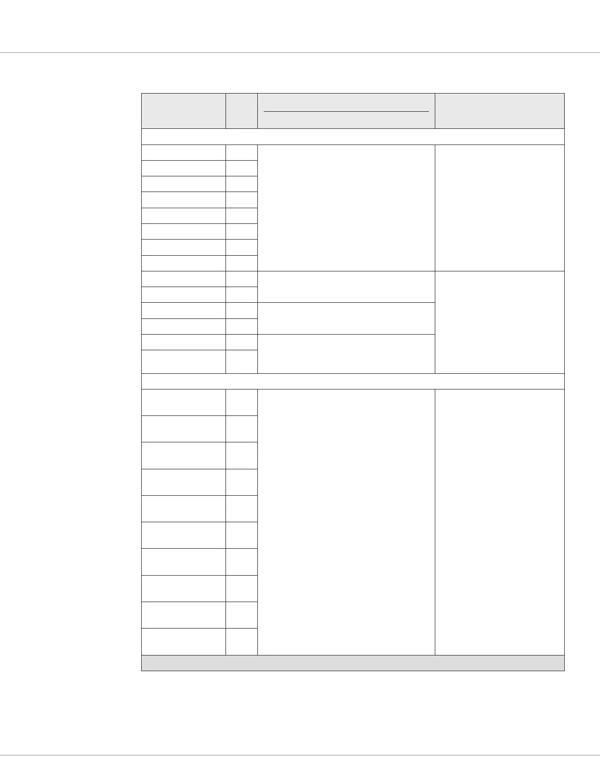
Table 8 Switch (digital) Inputs Electrical Specications
Signal Name Pin
Type
Logic Threshold
Input Impedance
TYPICAL DIGITAL (SWITCHED) INPUTS
Switch 1 13 Selectable Pull-up with xed Pull-down*
Fixed Pull-down:
> 23 kΩ (12-48V models)*
> 43 kΩ (36-96V models)*
Selectable Pull-up:
15kΩ to 15V
Switch 2 24
Low < 1 Volt
High > 4 Volts***
Switch 3 26
Switch 4 27
Switch 5 28
Switch 6 29
Switch 7 30
Switch 8 31
Switch 9 32
Selectable Pull-up or Pull-down*
> 660 kΩ (all models)*oat state
Switch 10 33
Switch 11 25
Low < 1 Volt
High > 4 Volts ***
Selectable Pull-down:
24kΩ for 12-48V controllers
47kΩ for 36-96V controllers
Selectable Pull-up:
15kΩ to 15V
Switch 12 34
Switch 13 ** 1
Note, Switch 13 (pin 1) and Switch 14 (pin 2)
are pulled-up to +5V as they are also used for
encoder 2
Switch 14 ** 2
VIRTUAL DIGITAL INPUTS
Virtual_Switch_1
(Analog 1)
1
Settings correspond with the associated
Analog Inputs
The Analog Inputs (5-10) have pull-up
resistors that can be enabled (tied to the
congured function of RTD and potentiometer
inputs).
> 178 kΩ
Virtual_Switch_2
(Analog 2)
2
Virtual_Switch_3
(Analog 3)
14
Virtual_Switch_4
(Analog 4)
15
Virtual_Switch_5
(Analog 5)
16
Virtual_Switch_6
(Analog 6)
17
Virtual_Switch_7
(Analog 7)
18
Virtual_Switch_8
(Analog 8)
19
Virtual_Switch_9
(Analog 9)
20
Virtual_Switch_10
(Analog 10)
21
*With the associated Driver = Off
* These pins have higher power pull-up or pull-down resistors that load the switch contact with approximately 1mA of current in
an attempt to create small arching to clean the connects and prevent high resistance build-up.
** S witch Inputs 13 and 14 must have the same Open State setting as their pull-up resistor enable is tied together.
*** The input voltage at the switch inputs should not be allowed to linger between the low and high threshold range. The state of
the switch will be unknown in this region.